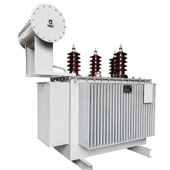
Earthing transformers, also called neutral couplers, are used in three-phase power systems where no neutral point is available or the neutral point is not brought out. They provide an artificial neutral point so that the system can be earthed directly, through a resistor, or through an arc suppression coil. This helps limit single-phase earth fault currents and suppress overvoltages on healthy phases.
Earthing transformers are classified as reactors in IEC 60076-6:2007. Their design depends on system operating conditions and substation requirements. Because existing literature gives limited guidance on testing, this paper discusses temperature rise testing for several common types of oil-immersed earthing transformers.
The general temperature rise test requirements shall follow IEC 60076-2:2011. For oil-immersed transformers with ONAN or ONAF cooling, the typical limits are 60 K for top-oil temperature rise and 65 K for average winding temperature rise, unless otherwise specified in the purchase specification.
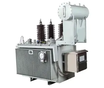
Zigzag Grounding/Earthing Transformer
2. Operating States and Temperature Rise Tests
2.1 Earthing Transformers with Rated Continuous Neutral Current and a Secondary Winding
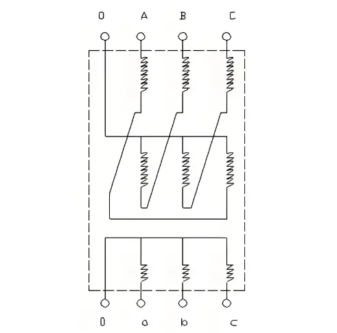
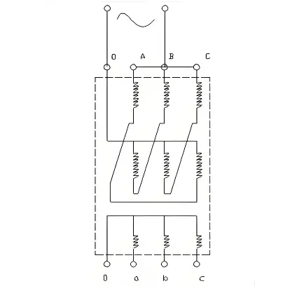
Grounding Transformer with Secondary Winding
For this type, the purchaser specifies the rated continuous neutral current based on the expected neutral point displacement and the selected neutral earthing method. A secondary winding may also be provided for substation auxiliary supply.
Under normal system conditions, the earthing transformer may operate in:
- a balanced three-phase load condition, where the neutral point remains close to earth potential;
- an unbalanced three-phase load condition, where neutral point displacement produces a continuous zero-sequence current;
- a secondary winding load condition.
Under balanced load, only excitation current flows in the primary winding. The losses are mainly core loss and a very small primary winding DC loss. The winding-to-oil temperature rise is therefore nearly zero.
When neutral point displacement occurs, a continuous zero-sequence current flows through the earthing transformer primary winding. This produces winding DC loss and additional stray loss caused by zero-sequence flux. If the secondary winding carries load, the secondary winding DC loss and additional load loss must also be considered.
Because the balanced condition and the neutral-displacement condition do not occur simultaneously, while the secondary load condition may be superimposed on either, the temperature rise test shall simulate the most severe combination.
Example test procedure
Assume an oil-immersed earthing transformer with the following data.
Example Technical Data of an Oil-Immersed Earthing Transformer
| Parameter |
Value |
| Vector group |
ZNyn11 |
| Rated current |
3.5 / 288.7 A |
| No-load loss |
1,337 W |
| Load loss at 75 °C based on 200 kVA |
969 W |
| LV winding DC loss at 75 °C |
754 W |
| Rated continuous neutral current |
70 A |
| Loss at rated continuous neutral current at 75 °C |
4,930 W |
The temperature rise test may be carried out as follows.
Step 1 — Maximum total loss stage
The total loss to be applied is:
Pmax = PkN(75 °C) + P0 + Pr(75 °C)
Pmax = 4,930 + 1,337 + 754 = 7,021 W
where:
- PkN(75 °C) is the loss produced by the rated continuous neutral current;
- P0 is the no-load loss at rated voltage and frequency;
- Pr(75 °C) is the LV winding DC loss at rated secondary load current.
The loss produced by the rated continuous neutral current shall be based on measured values. Before the test, the secondary winding is kept open-circuited, and the rated continuous neutral current of 70 A is applied between the HV terminals ABC and the neutral point O. The measured loss is then corrected to the reference temperature of 75 °C.
Earthing Transformer Temperature Rise Test Connection
Pr(75 °C) is the LV winding DC loss at the rated secondary current of 288.7 A. The HV current corresponding to the 200 kVA secondary load is 3.5 A, which is already included in the 70/3 A per phase. Therefore, the full load loss measured in a conventional load test shall not be used directly, otherwise the HV DC loss would be applied twice and the temperature rise result would be overstated.
After the total loss is determined, the transformer is energised according to the test wiring diagram. The top-oil temperature rise and average oil temperature rise are obtained in accordance with IEC 60076-2:2011.
Step 2 — HV winding temperature rise
The current for this stage shall include the rated continuous neutral current and the HV current corresponding to the rated secondary capacity. For this example, the applied current is:
I = 3 × 3.5 + 70 = 80.5 A
This current is maintained for one hour. The hot resistance of the HV winding between terminal B and neutral O is measured to determine the HV winding-to-oil temperature difference and hence the HV winding temperature rise. This approach follows the principle given in IEC 60076-6:2007 for earthing transformers with a secondary winding.
Step 3 — LV winding temperature rise
The earthing transformer is then treated similarly to a distribution transformer for the LV winding test. The LV winding is short-circuited, and a symmetrical three-phase current of 3.5 A is applied to the HV side, corresponding to the rated secondary capacity. The test duration is one hour.
The LV winding hot resistance and average oil temperature are measured. The LV winding-to-oil temperature difference is calculated and added to the average oil temperature rise obtained in Step 1 to determine the LV winding temperature rise.
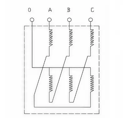
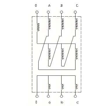
Grounding Transformer without Secondary Winding
2.2 Earthing Transformers with Rated Continuous Neutral Current but without a Secondary Winding
This type covers the balanced condition and the neutral-displacement condition. The temperature rise test shall represent the neutral-displacement condition.
The test parameters are:
- Maximum total loss stage: Pmax = PkN(75 °C) + P0
- Rated current stage: I = IN
2.3 Earthing Transformers Combined with Arc Suppression Coils
For this type, the arc suppression coil is integrated at the transformer neutral point. The earthing transformer and the arc suppression coil shall be tested together. If the arc suppression coil is adjustable, the test shall be performed at the position producing the highest loss.
Combination of Arc Suppression Coil and Earthing Transformer
The methods for determining maximum total loss and rated current are the same as in Section 2.1. Hot resistance measurements shall be made twice:
- Between one line terminal and the arc suppression coil earth terminal, usually BO;
- Between two line terminals of the earthing transformer, usually AC.
These measurements allow the temperature differences of the main earthing transformer winding and the arc suppression coil winding to be determined separately.
3. Conclusion
Temperature rise is a key performance indicator for the safe operation and service life of earthing transformers. Because earthing transformers have diverse structures and operating modes, incorrect test methods may lead to misleading results. By simulating the most severe operating conditions in accordance with IEC 60076-6:2007 and IEC 60076-2:2011, manufacturers can obtain more reliable temperature rise data for oil-immersed earthing transformers.

 Login