Technical Field
The utility model relates to the technical field of ring main units, specifically an air-insulated intelligent vacuum ring main unit.
Background Art
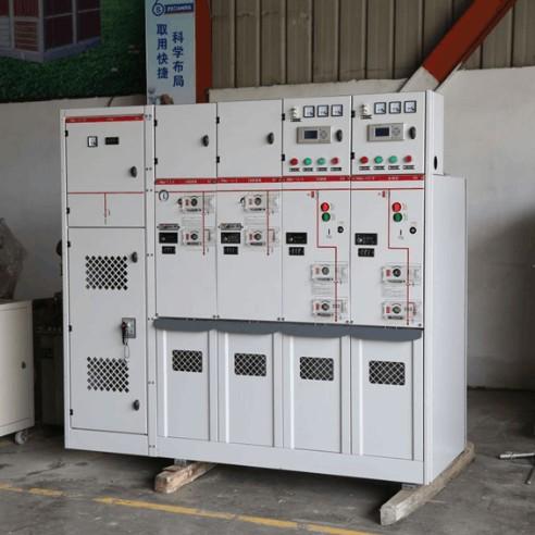
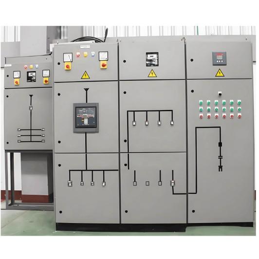
A ring main unit is an electrical device that integrates high-voltage switchgear into a metal enclosure or assembles it into a interval-type ring main power supply unit. It forms a system by connecting the busbars of various outgoing feeder cabinets, with its core comprising load switches and fuses. It features simple structure, small size, low cost, excellent power supply parameters, and high safety.
Air-insulated ring main units (also known as semi-insulated ring main units) use dry air as the insulation and arc-extinguishing medium. Their performance is superior to SF6 gas without causing environmental pollution. The high-voltage live switches are housed in a sealed air chamber with constant pressure unaffected by the environment, making them suitable for special areas like plateaus, salt-alkali regions, and humid locations.
In existing technology, air-insulated ring main units often adopt combination forms such as load switch-disconnector, load switch-high-voltage fuse, and vacuum circuit breaker-disconnector. Unit cabinets can be used individually or freely combined. However, the following shortcomings exist:
When combined, the operating status is only displayed via the relay and instrument compartment, requiring regular manual inspections and troubleshooting, which incurs high costs.
Heat dissipation within the cabinet is difficult to resolve effectively: Relying solely on internal air circulation cannot dissipate heat efficiently, while a simple ventilation hole structure is prone to introducing excessive moisture, affecting electrical safety. Improvement is urgently needed.
Utility Model Content
Objective
Aiming at the defects of the existing technology, the utility model provides an air-insulated intelligent vacuum ring main unit, aiming to achieve:
A rational layout to expand busbar combination functionality.
Real-time monitoring of the operating status, improving intelligent management levels, and reducing maintenance costs.
Optimized heat dissipation performance while avoiding moisture introduction, balancing electrical safety and energy efficiency.
Technical Solution
An air-insulated intelligent vacuum ring main unit comprises a cabinet body with the following internal structure:
Core Functional Areas and Components
The cabinet body includes a busbar compartment, a relay and instrument compartment, a switch compartment, and a cable compartment:
Busbar Compartment: Contains busbars, a first temperature sensor, and a fan set electrically connected to a PLC controller.
Relay and Instrument Compartment: Located on one side of the busbar compartment, housing relays.
Switch Compartment: Located at the bottom of the busbar compartment, housing a load switch set, a second temperature sensor, and a humidity sensor (the humidity sensor is located on one side of a first partition plate and connected to a data storage module). The load switch set is connected to the busbar compartment via an insulator set comprising three interval insulators and is connected to fuses, an operating mechanism, and a current transformer. A frame is provided between the current transformer and the cabinet body.
A control compartment and an air chamber are located on one side of the switch compartment:
Control Compartment: Situated between the relay and instrument compartment and the air chamber, housing a circuit board and the PLC controller. The circuit board integrates the data storage module, a wireless transmission module, and a wireless reception module. The data storage module is connected to the relays, the first temperature sensor, the second temperature sensor, and the wireless transmission module. The wireless reception module is connected to the PLC controller.
Air Chamber: One side is connected to the switch compartment via the first partition plate, and the other side has an air inlet mesh facing the cabinet body. The first partition plate is provided with a return air outlet and a supply air outlet,equipped with a first fan and a second fan respectively (both electrically connected to the PLC controller). The first fan is connected to a moisture absorption plate, which is located between the second fan and the air inlet mesh.
Cable Compartment: Houses an interconnected earthing switch, lightning arrester, and cable.
Cabinet Body and Profile Structure
Second partition plates are provided between the busbar compartment and the relay & instrument compartment/switch compartment, and between the switch compartment and the control compartment/cable compartment.
The cabinet body is composed of several riveted frame plates. Both the frame plates and the frame use a profile body:
The four corners of the profile body are provided with plug-in blocks. The outer wall of the plug-in block is inclined relative to the profile body, with a first through hole inside and limit plates on both sides.
The center of the profile body has a second through hole. The cross-section of its top and bottom is an isosceles trapezoid, and both sides are concave arcs.
Both sides of the profile body are provided with concave arc plates, which have several waist-shaped mounting holes.
Beneficial Effects
Structural Advantages: The profile body with plug-in blocks and concave arc plates, along with the first through hole and the specially shaped second through hole, ensures high rigidity and stability while reducing wall thickness. The waist-shaped mounting holes facilitate quick assembly and subsequent sensor embedding/wiring. The overall structure is novel, compact, and easy to assemble.
Layout Optimization: The relay and instrument compartment, control compartment, and air chamber are distributed on the same side, combined and connected with the switch compartment and busbar compartment, effectively expanding busbar functions, avoiding wiring confusion, and providing high space utilization.
Intelligent Control:
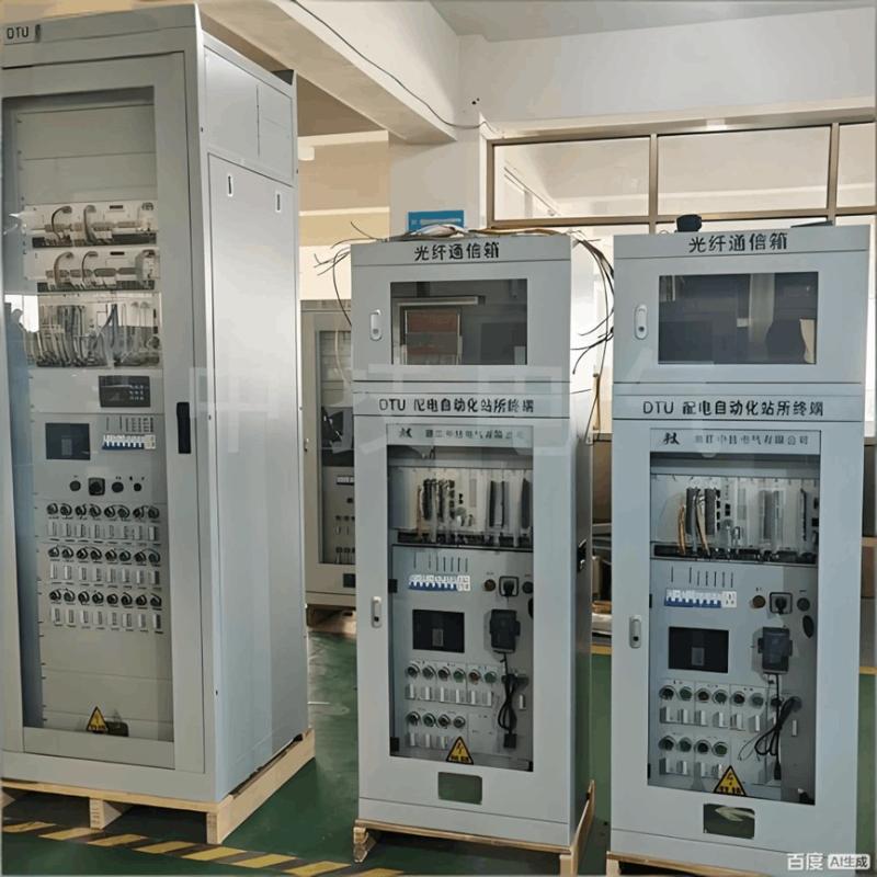
The data storage module sends circuit status and environmental data collected by the relays, temperature sensors (first and second), and humidity sensor in real-time via the wireless transmission module, facilitating integrated monitoring of connected cabinets, improving intelligent management, and reducing maintenance costs.
After the wireless reception module receives a control signal, the PLC controller activates as needed: the fan set for internal circulation heat dissipation, or the second fan to draw in external air through the moisture absorption plate for external circulation cooling.When the temperature is low, only the first fan can be activated, using hot air from the switch compartment to dehumidify the moisture absorption plate. This enhances energy efficiency, avoids moisture introduction, and balances electrical safety with energy savings.
Detailed Implementation Mode
I. Cabinet Structure and Core Components
Functional Area Division
The cabinet interior includes the busbar compartment, relay and instrument compartment, switch compartment, cable compartment,control compartment, and air chamber. Each area is separated by partition plates, with clear functions and no interference.
The busbar compartment is located in the upper part, with the relay and instrument compartment on one side and the switch compartment at the bottom. One side of the switch compartment sequentially has the control compartment and the air chamber, while the other side is the cable compartment.
Core Components of Each Area
Busbar Compartment: Contains busbars, the first temperature sensor, and the fan set electrically connected to the PLC controller.
Relay and Instrument Compartment: Houses relays for collecting equipment operating status (e.g., current, voltage, power).
Switch Compartment: Equipped with the load switch set, the second temperature sensor, and the humidity sensor. The load switch set is connected to the busbar compartment via the insulator set (with three interval insulators) and is connected to fuses, the operating mechanism, and the current transformer. A frame is provided between the current transformer and the cabinet body.
Control Compartment: Contains the circuit board and the PLC controller. The circuit board integrates the data storage module, wireless transmission module, and wireless reception module. The data storage module is connected to the relays, the first temperature sensor, the second temperature sensor, and the humidity sensor. The wireless reception module is connected to the PLC controller.
Air Chamber: One side is connected to the switch compartment via the first partition plate, and the other side has the air inlet mesh. The first partition plate has a return air outlet and a supply air outlet, equipped with the first fan and second fan respectively (both electrically connected to the PLC controller). The first fan is connected to the moisture absorption plate,located between the second fan and the air inlet mesh.
Cable Compartment: Houses the interconnected earthing switch, lightning arrester, and cable.
Cabinet Body and Profile Structure
The cabinet body is formed by riveting several frame plates. Both the frame plates and the frame use the profile body.
The four corners of the profile body have plug-in blocks. The outer wall of the plug-in block is inclined relative to the profile body, with a first through hole inside and limit plates on both sides. The center has a second through hole; its top and bottom cross-section is an isosceles trapezoid, and both sides are concave arcs. Both sides of the profile body also have concave arc plates with several waist-shaped mounting holes.
II. Working Principle and Advantages
Assembly Method
The profile bodies achieve quick connection via the plug-in blocks with limit plates, and are then riveted and fixed using corner connecting pieces through the waist-shaped mounting holes on the concave arc plates. The assembly process is convenient and stable, also providing shock resistance, lower cost and weight, and ease of transportation.
Operation and Intelligent Control Process
The busbar compartment connects multiple ring main units. The load switch set connects to the busbar compartment via the insulator set. The fuse disconnects the circuit by melting its element when current exceeds the limit. The operating mechanism performs closing and opening operations. The current transformer proportionally converts a large primary current to a small secondary current, protecting the measurement circuit, and transmits signals to the earthing switch, lightning arrester, and cable in the cable compartment.
The relays collect equipment operating status and transmit it to the data storage module on the circuit board. This module also stores temperature signals from the first and second temperature sensors and the humidity signal from the humidity sensor. These are then sent in real-time via the wireless transmission module to a base station or control terminal for remote monitoring.
The control terminal can send commands to the PLC controller via the wireless reception module, or the PLC controller can make automatic judgments: When heat dissipation is needed, it activates the fan set for internal circulation heat dissipation, or starts the second fan to draw air through the inlet mesh, dehumidify it via the moisture absorption plate, and supply it into the cabinet for external circulation heat dissipation. When the temperature does not meet the condition for starting the second fan, only the first fan can be activated to dehumidify the moisture absorption plate, reducing energy consumption while avoiding moisture introduction.
Core Advantages
Real-time monitoring and intelligent control of the cabinet's temperature, humidity, and equipment operating status are achieved. This ensures electrical safety while reducing energy consumption by activating equipment on demand, balancing practicality and energy efficiency.