技術分野
本実用新案はリングメインユニットの技術分野に関し、具体的には空気絶縁型スマート真空リングメインユニットに関するものである。
背景技術
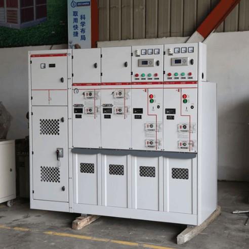
リングメインユニットは、高圧スイッチギアを金属製の箱体に組み込んだり、間隔タイプのリングメイン電源ユニットとして組み立てたりする電気機器である。これは、各出力フィーダーキャビネットのバスバーを接続することでシステムを形成し、そのコアは負荷スイッチとヒューズで構成されている。シンプルな構造、小型、低コスト、優れた供給パラメータ、高い安全性が特徴である。
空気絶縁型リングメインユニット(半絶縁型リングメインユニットとも呼ばれる)は、乾燥した空気を絶縁および消弧媒体として使用する。その性能はSF6ガスよりも優れており、環境汚染も引き起こさない。高圧のライブスイッチは、環境の影響を受けずに一定の圧力を保つ密封された空気室に収容されており、高原、塩アルカリ地域、湿った場所などの特殊な地域でも適している。
既存の技術では、空気絶縁型リングメインユニットは、負荷スイッチ-遮断器、負荷スイッチ-高圧ヒューズ、真空回路ブレーカー-遮断器などの組み合わせ形式を採用することが多い。ユニットキャビネットは単独で使用することも自由に組み合わせることもできるが、以下の欠点がある:
組み合わせた場合、動作状態はリレーと計器室でのみ表示され、定期的な手動による点検とトラブルシューティングが必要であり、コストがかかる。
キャビネット内の熱放散が効果的に解決できない:内部の空気循環だけでは効率的に熱を放出できず、単純な通気孔構造は過度の湿気を導入しやすく、電気安全に影響を与えるため、改善が急務である。
実用新案の内容
目的
本実用新案は、既存の技術の欠点に対処するために、空気絶縁型スマート真空リングメインユニットを提供し、以下の目標を達成することを目指す:
合理的なレイアウトにより、バスバーの組み合わせ機能を拡張する。
動作状態のリアルタイム監視を行い、インテリジェントな管理レベルを向上させ、メンテナンスコストを削減する。
熱放散性能を最適化しながら湿気の導入を避けることで、電気安全とエネルギー効率のバランスを取る。
技術的解決手段
空気絶縁型スマート真空リングメインユニットは、以下の内部構造を持つキャビネット本体から構成される:
コア機能領域とコンポーネント
キャビネット本体には、バスバーコンパートメント、リレーと計器コンパートメント、スイッチコンパートメント、ケーブルコンパートメントが含まれる:
バスバーコンパートメント: バスバー、第一温度センサー、PLCコントローラーに電気的に接続されたファンセットを含む。
リレーと計器コンパートメント: バスバーコンパートメントの一方に位置し、リレーを収容する。
スイッチコンパートメント: バスバーコンパートメントの底部に位置し、負荷スイッチセット、第二温度センサー、湿度センサー(湿度センサーは第一パーティションプレートの一方に位置し、データ記憶モジュールに接続されている)を収容する。負荷スイッチセットは、三つの間隔絶縁子で構成される絶縁セットを介してバスバーコンパートメントに接続され、ヒューズ、操作機構、電流変換器に接続される。電流変換器とキャビネット本体の間にフレームが設けられている。
制御コンパートメントとエアチャンバーは、スイッチコンパートメントの一方に位置する:
制御コンパートメント: リレーと計器コンパートメントとエアチャンバーの間に位置し、基板とPLCコントローラーを収容する。基板はデータ記憶モジュール、無線送信モジュール、無線受信モジュールを統合している。データ記憶モジュールはリレー、第一温度センサー、第二温度センサー、無線送信モジュールに接続されている。無線受信モジュールはPLCコントローラーに接続されている。
エアチャンバー: 一方は第一パーティションプレートを介してスイッチコンパートメントに接続され、他方はキャビネット本体に向けてエアインレットメッシュを持っている。第一パーティションプレートにはリターンエアアウトレットとサプライエアアウトレットがあり、それぞれ第一ファンと第二ファン(両方ともPLCコントローラーに電気的に接続されている)が装備されている。第一ファンは吸湿プレートに接続され、これは第二ファンとエアインレットメッシュの間に位置している。
ケーブルコンパートメント: 接地スイッチ、雷保護器、ケーブルを収容する。
キャビネット本体とプロファイル構造
第二パーティションプレートは、バスバーコンパートメントとリレー&計器コンパートメント/スイッチコンパートメントの間、およびスイッチコンパートメントと制御コンパートメント/ケーブルコンパートメントの間に設けられている。
キャビネット本体はいくつかのリベット接続されたフレームプレートで構成されている。フレームプレートとフレームはプロファイルボディを使用する:
プロファイルボディの四隅にはプラグインブロックが設けられており、プラグインブロックの外壁はプロファイルボディに対して傾斜しており、内部には第一貫通孔があり、両側に制限プレートがある。
プロファイルボディの中心には第二貫通孔があり、その上部と下部の断面は二等辺台形で、両側は凹アーチである。
プロファイルボディの両側には凹アーチプレートが設けられており、複数のウェストシェープド取り付け穴がある。
有益な効果
構造上の利点: プラグインブロックと凹アーチプレート、第一貫通孔と特別形状の第二貫通孔を備えたプロファイルボディは、壁厚を減らしつつ高い剛性と安定性を確保する。ウェストシェープド取り付け穴は迅速な組み立てと後続のセンサ埋め込み/配線を可能にする。全体の構造は新しく、コンパクトで組み立てやすい。
レイアウトの最適化: リレーと計器コンパートメント、制御コンパートメント、エアチャンバーは同じ側に配置され、スイッチコンパートメントとバスバーコンパートメントと組み合わせて接続することで、バスバー機能を効果的に拡張し、配線の混乱を避け、高い空間利用効率を提供する。
インテリジェントな制御:
データ記憶モジュールは、リレー、温度センサー(第一と第二)、湿度センサーによって収集された回路状態と環境データを無線送信モジュールを通じてリアルタイムで送信し、接続されたキャビネットの統合監視を可能にし、インテリジェントな管理を向上させ、メンテナンスコストを削減する。
無線受信モジュールが制御信号を受信すると、PLCコントローラーは必要に応じてアクティブ化する:内部循環熱放散のためにファンセットを起動するか、外部からの空気を吸湿プレートを通じて引き込むために第二ファンを起動する。温度が低い場合、第一ファンのみを起動し、スイッチコンパートメントからの温風を利用して吸湿プレートを除湿することができる。これによりエネルギー効率が向上し、湿気の導入を避けることができ、電気安全とエネルギー節約のバランスを取ることができる。
詳細な実施形態
I. キャビネット構造とコアコンポーネント
機能領域の分割
キャビネット内には、バスバーコンパートメント、リレーと計器コンパートメント、スイッチコンパートメント、ケーブルコンパートメント、制御コンパートメント、エアチャンバーが含まれる。各領域はパーティションプレートによって区切られ、機能が明確で干渉しない。
バスバーコンパートメントは上部に位置し、リレーと計器コンパートメントは一方に、スイッチコンパートメントは底部にある。スイッチコンパートメントの一方には順に制御コンパートメントとエアチャンバーがあり、他方はケーブルコンパートメントである。
各領域のコアコンポーネント
バスバーコンパートメント: バスバー、第一温度センサー、PLCコントローラーに電気的に接続されたファンセットを含む。
リレーと計器コンパートメント: 設備の動作状態(例:電流、電圧、電力)を収集するリレーを収容する。
スイッチコンパートメント: 負荷スイッチセット、第二温度センサー、湿度センサーを装備する。負荷スイッチセットは、三つの間隔絶縁子で構成される絶縁セットを介してバスバーコンパートメントに接続され、ヒューズ、操作機構、電流変換器に接続される。電流変換器とキャビネット本体の間にフレームが設けられている。
制御コンパートメント: 基板とPLCコントローラーを収容する。基板はデータ記憶モジュール、無線送信モジュール、無線受信モジュールを統合している。データ記憶モジュールはリレー、第一温度センサー、第二温度センサー、湿度センサーに接続されている。無線受信モジュールはPLCコントローラーに接続されている。
エアチャンバー: 一方は第一パーティションプレートを介してスイッチコンパートメントに接続され、他方はエアインレットメッシュを持っている。第一パーティションプレートにはリターンエアアウトレットとサプライエアアウトレットがあり、それぞれ第一ファンと第二ファン(両方ともPLCコントローラーに電気的に接続されている)が装備されている。第一ファンは吸湿プレートに接続され、これは第二ファンとエアインレットメッシュの間に位置している。
ケーブルコンパートメント: 接地スイッチ、雷保護器、ケーブルを収容する。
キャビネット本体とプロファイル構造
キャビネット本体はいくつかのフレームプレートをリベット接続して形成される。フレームプレートとフレームはプロファイルボディを使用する。
プロファイルボディの四隅にはプラグインブロックがあり、プラグインブロックの外壁はプロファイルボディに対して傾斜しており、内部には第一貫通孔があり、両側に制限プレートがある。中央には第二貫通孔があり、その上部と下部の断面は二等辺台形で、両側は凹アーチである。プロファイルボディの両側にも凹アーチプレートがあり、複数のウェストシェープド取り付け穴がある。
II. 動作原理と利点
組立方法
プロファイルボディは、制限プレート付きのプラグインブロックを介して素早く接続され、その後、コーナー接続部品を使用して凹アーチプレートのウェストシェープド取り付け穴を通じてリベット固定される。組立過程は便利かつ安定しており、衝撃耐性があり、コストと重量が低く、輸送も容易である。
動作とインテリジェント制御プロセス
バスバーコンパートメントは複数のリングメインユニットを接続する。負荷スイッチセットは絶縁セットを介してバスバーコンパートメントに接続される。ヒューズは、電流が制限を超えたときに要素が溶けて回路を切断する。操作機構は閉鎖と開放を行う。電流変換器は大電流を小電流に比例して変換し、測定回路を保護し、接地スイッチ、雷保護器、ケーブルコンパートメントのケーブルに信号を伝送する。
リレーは設備の動作状態を収集し、それを基板上のデータ記憶モジュールに送信する。このモジュールはまた、第一と第二温度センサーからの温度信号と湿度センサーからの湿度信号も記録し、これらを無線送信モジュールを通じて基地局や制御端末にリアルタイムで送信し、遠隔監視を行う。
制御端末は無線受信モジュールを通じてPLCコントローラーにコマンドを送ることができ、またはPLCコントローラーが自動的に判断する:熱放散が必要な場合、内部循環熱放散のためにファンセットを起動するか、エアインレットメッシュを通じて外部の空気を取り込み、吸湿プレートを介して除湿し、キャビネット内に供給して外部循環熱放散を行うために第二ファンを起動する。温度が第二ファンの起動条件を満たしていない場合、第一ファンのみを起動して吸湿プレートを除湿し、エネルギー消費を削減しながら湿気の導入を避けることができる。
核心的な利点
キャビネットの温度、湿度、設備の動作状態のリアルタイム監視とインテリジェント制御が達成される。これにより、必要に応じて設備をアクティブ化することでエネルギー消費を削減し、実用性とエネルギー効率のバランスを取ることができる。