1. Selection of Test Instruments
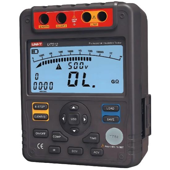
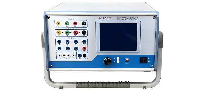
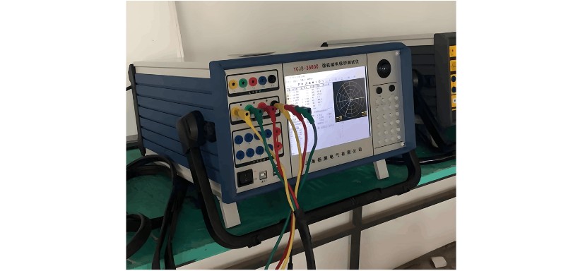
The main test instruments for microcomputer protection devices are: microcomputer relay protection tester, three-phase current generator, and multimeter.
For testing high-voltage microcomputer protection devices, it is recommended to use a microcomputer relay protection tester capable of simultaneously outputting three-phase voltage and three-phase current, and equipped with timing function for digital inputs.
For testing low-voltage microcomputer protection devices, if the current sampling signal is delivered to the protection device via a current transformer (CT), a microcomputer relay protection tester can be used. However, if the current sampling signal is fed directly into the protection device through a dedicated sensor, a three-phase current generator must be used to apply test current on the primary side.
2. Precautions During Testing
Both the test instrument and the cabinet must be reliably grounded to ensure the microcomputer protection device and the tester share a common ground.
Do not insert or remove device modules, or touch circuit boards, while the microcomputer protection device is powered on or during testing. If module replacement is necessary, power must first be turned off, external test power disconnected, and personnel must discharge body static or wear anti-static wrist straps before proceeding.
During testing, never accidentally apply high voltage to low-voltage or communication terminals when changing test leads.
Test point selection must be accurate. Voltage and current leads from the tester should not be connected directly to the protection device terminals, but rather to the primary side of the instrument transformers. This allows evaluation of signal attenuation during acquisition and ensures test completeness.
3. Preparations Before Testing
Carefully read the microcomputer protection device manual or test procedure. Verify consistency among the manual, device nameplate, actual wiring diagrams, and the system’s voltage and current transformer ratios.
Thoroughly read the microcomputer protection tester manual and become proficient in its operation before testing. Avoid incorrect operations that could subject the protection device to excessive voltage or current, potentially causing damage.
Secure all screws and quick-connect modules of the protection device to ensure reliable connections.
Access the protection menu to set protection settings. Fully understand the meaning of each setting value, organize and label the setting sheet for easy verification later.
4. AC Circuit Calibration
Apply test current at the secondary side of the CT in the cabinet according to the wiring diagram. Mark and store removed bolts properly. Voltage analog testing can be performed at terminal blocks, but ensure voltage does not propagate to busbars.
Adjust the magnitude and phase of voltage and current on the tester. After applying test values, record both the sampling values displayed on the device’s LCD and the actual values from the tester. The error between the two should be less than ±5%. Record data at three points: ascending (0%, 50%, 100%) and descending (100%, 50%, 0%). The displayed values should show no significant difference between up and down tests. Use the following table format for recording.
5. Digital Input/Output (DI/DO) Checks
Digital input/output checks should be performed together with functional tests.
5.1. Digital Input (DI) Check
Digital inputs of microcomputer protection devices include two types. The first is hard contact inputs—external switch contacts directly connected to the device. When the external contact closes, the corresponding defined signal appears on the display. The second is soft contact inputs—internal logic responses, such as a "overcurrent trip" signal displayed on the panel when an overcurrent fault occurs.
DI checks must be performed one by one according to the drawings. Operate associated equipment to change contact states. The displayed status on the LCD or cabinet indicator lights should change accordingly. To ensure reliable operation, each digital input should be tested at least three times.
Never simulate contact closure directly at the backplane terminals of the protection device. Only when the system fails to display or incorrectly displays equipment status should terminal simulation be used to determine whether the fault lies in the protection device, wiring, or equipment.
5.2. Digital Output (DO) Check
DO contacts are also divided into hard and soft types. Hard DO status can be measured with a multimeter. Soft DO status changes must be judged based on logical behavior.
5.3. Digital Signal Checks
Alarm Signal Contact Check: Simulate corresponding faults according to logic. If an alarm is expected but not displayed or incorrect, the device is faulty. For example, simulating a PT fuse failure should result in "PT fuse failure alarm" on the LCD, illumination of the "Alarm" LED, and activation of the "Signal Relay." Alarm signal contacts are momentary.
Trip Signal Contact Check: Trip signal contacts are soft contacts. After a protection trip action, the LCD should display "xx protection trip," the CPU should illuminate the "Trip" LED, and activate the corresponding "Trip Signal Relay." The trip LED and central signal contacts are latching (maintained).
Trip Output Contact Check: Trip output contacts are hard contacts. After a trip action, the protection device activates the trip output relay, closing the trip output contact. These contacts are latching (maintained).
6. Protection Function Testing
Protection function testing is the core of microcomputer protection device testing, focusing on verifying correct setting values, trip time, and output performance.
Definite-Time Protection Testing
Approach Method: Disable other protection functions to prevent false tripping. Set the time delay to 0s. Use the tester to approach the set trip value in 0.1A steps until the device issues a trip command. Record the actual operating value, which should be within ±5% of the set value. Then set the time delay to the specified value and apply the recorded actual operating value. The measured trip time should also be within ±5% of the set time.
Fixed-Value Method: Disable other protections. Apply 0.95×, 1.05×, and 1.2× the set trip value. Protection should not operate at 0.95×, must operate at 1.05×, and trip time should be tested at 1.2×. The measured time should be within ±5% of the set time.
6.2. Inverse-Time Protection Testing
Disable other protections. Apply a test value corresponding to a point on the inverse-time curve. Measure the protection operation time and compare it with the theoretical time calculated from the formula. The error should be within ±5%. It is recommended to test at five different points.
Post-Test Verification
Verify Setting Values: Due to frequent enabling/disabling during testing, confusion may occur. After completing all tests, two personnel should jointly verify all settings.
Restore Removed Wiring: Restore all disconnected wires according to drawings or markings, ensuring correct reconnection. When restoring current circuits, avoid reversing CT polarity or connecting protection wires to measurement circuits.
Check Terminal Block Links: Reconnect any opened links on terminal blocks and have them inspected by a designated person. Even if connected, tighten with a screwdriver to prevent loose connections.
Tighten All Core Wire Terminals: To prevent loosening during testing, all wire terminals must be re-tightened after testing to ensure secure crimping.


