What is Owen’s Bridge?

Owen's Bridge: Definition and Principle
Owen's bridge is defined as an electrical bridge specifically designed to measure inductance by relating it to capacitance. At its core, it operates on the principle of comparison, where the value of an unknown inductor is systematically evaluated by juxtaposing it against a standard capacitor. This methodical approach enables precise determination of the inductance value through the establishment of electrical equivalences between the two components.
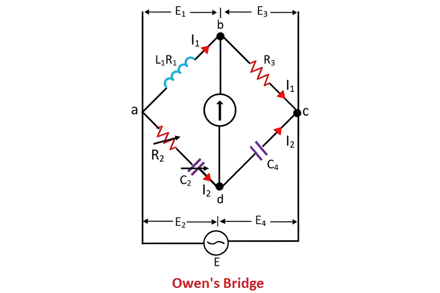
The connection diagram of Owen's bridge, as illustrated in the accompanying figure, showcases the specific arrangement of its various electrical elements. This diagram serves as a visual guide to understanding how the bridge circuit is configured, highlighting the interconnections between the inductor under test, the standard capacitor, and other associated components. Through this carefully designed setup, Owen's bridge facilitates accurate and reliable measurements of inductance, making it an essential tool in electrical engineering for characterizing inductive components.
Owen's Bridge: Circuit Configuration and Balanced State
In Owen's bridge, the circuit is composed of four distinct arms labeled as ab, bc, cd, and da. The ab arm is purely inductive, housing the unknown inductor L1 that needs to be measured. The bc arm, in contrast, exhibits purely resistive characteristics. The cd arm features a fixed capacitor C4, while the ad arm contains a combination of a variable resistor R2 and a variable capacitor C2, both connected in series within the circuit.
The fundamental operation of Owen's bridge involves comparing the unknown inductor L1 in the ab arm with the known capacitor C4 in the cd arm. To achieve a balanced state in the bridge, the resistor R2 and the capacitor C2 are adjusted independently. When the bridge reaches this balanced condition, a key indicator is that no current flows through the detector placed between points b and c. This absence of current signifies that the endpoints b and c of the detector are at the same electrical potential, establishing the necessary equilibrium for accurate measurement.
Phasor Diagram of Owen's Bridge
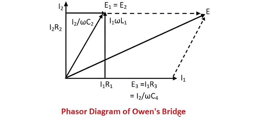
The phasor diagram of Owen's bridge, depicted in the figure below, provides a visual representation of the electrical quantities and their phase relationships within the bridge circuit. It offers valuable insights into how the voltages and currents interact at different points in the circuit, especially during the balanced state, facilitating a deeper understanding of the bridge's operational principles and the underlying electrical phenomena.
Phasor Analysis and Theory of Owen's Bridge
In Owen's bridge, the current I1, along with the voltages E3 = I3 R3 and E4=ω I2 C4, all share the same phase. These quantities are represented along the horizontal axis of the phasor diagram, signifying their in - phase relationship. Similarly, the voltage drop I1 R1 across the arm ab is also plotted on the horizontal axis, reflecting its phase alignment with the other horizontally - oriented phasors.
The total voltage drop E1 across the arm ab is the result of combining two components: the inductive voltage drop ω L1 I1 and the resistive voltage drop I1 R1. When the bridge attains a balanced state, the voltages E1 and E2 across the arms ab and ad, respectively, become equal in magnitude and phase. Consequently, they are depicted on the same axis in the phasor diagram, emphasizing the equilibrium condition of the bridge circuit.
The voltage drop V2 across the arm ad is composed of two parts: the resistive voltage drop I2 R2 and the capacitive voltage drop I2 ω C2. Due to the presence of the fixed capacitor C4 in the arm cd, the current I2 flowing through the arm ad leads the voltage drop V4 across the arm cd by 90 degrees. This phase difference is a key characteristic of the capacitive - inductive interaction within the bridge circuit.
The current I2 and the voltage I2 R2 are represented on the vertical axis of the phasor diagram, as illustrated in the figure. The supply voltage of the bridge is obtained by the phasor addition of the voltages V1 and V3, which combines the electrical contributions from different parts of the circuit.
Theory of Owen's Bridge
Let:
At the balance condition of Owen's bridge,
I2 C4, all share the same phase. These quantities are represented along the horizontal axis of the phasor diagram, signifying their in - phase relationship. Similarly, the voltage drop I1 R1 across the arm ab is also plotted on the horizontal axis, reflecting its phase alignment with the other horizontally - oriented phasors.
The total voltage drop E1 across the arm ab is the result of combining two components: the inductive voltage drop ωL1 I1 and the resistive voltage drop I1 R1. When the bridge attains a balanced state, the voltages E1 and E2 across the arms ab and ad, respectively, become equal in magnitude and phase. Consequently, they are depicted on the same axis in the phasor diagram, emphasizing the equilibrium condition of the bridge circuit.
The voltage drop V2 across the arm ad is composed of two parts: the resistive voltage drop I2 R2 and the capacitive voltage drop I2 C2. Due to the presence of the fixed capacitor C4 in the arm cd, the current I2 flowing through the arm ad leads the voltage drop V4 across the arm cd by 90 degrees. This phase difference is a key characteristic of the capacitive - inductive interaction within the bridge circuit.
The current I2 and the voltage I2 R2 are represented on the vertical axis of the phasor diagram, as illustrated in the figure. The supply voltage of the bridge is obtained by the phasor addition of the voltages V1 and V3, which combines the electrical contributions from different parts of the circuit.
Theory of Owen's Bridge
Let:
At the balance condition of Owen's bridge,

On separating the real and imaginary part we get,

And,

Advantages and Disadvantages of Owen's Bridge
Advantages of Owen's Bridge
Owen's bridge offers several notable benefits, making it a valuable tool in electrical measurements:
Disadvantages of Owen's Bridge
Despite its advantages, Owen's bridge also has some limitations:
Modifications to Owen's Bridge
To address some of its inherent limitations or adapt it to different measurement requirements, Owen's bridge can be modified. One common modification involves connecting a voltmeter in parallel with the resistive arms of the bridge. This setup allows for the application of both direct and alternating current supplies to the bridge. An ammeter is connected in series with the bridge to measure the direct current, while the alternating current is measured using the voltmeter. These modifications enhance the bridge's functionality and enable more comprehensive electrical measurements, although they may also introduce additional complexity to the overall circuit setup.
Recommended


