Ano ang Owen’s Bridge?

Puente ni Owen: Definisyon at Prinsipyo
Ang puente ni Owen ay isang elektrikal na puente na espesyal na disenyo upang sukatin ang inductance sa pamamagitan ng pag-uugnay nito sa capacitance. Sa kanyang pinakamahalagang prinsipyo, ito ay gumagana sa pamamaraan ng pagsusunod-sunod, kung saan ang halaga ng hindi alam na inductor ay sistematikong pinag-aaralan sa pamamagitan ng paghahambing nito sa isang pamantayan na kapasitor. Ang sistemang ito ay nagbibigay-daan para sa tumpak na pagtukoy ng halaga ng inductance sa pamamagitan ng pagtatatag ng elektrikal na katumbas ng dalawang komponente.
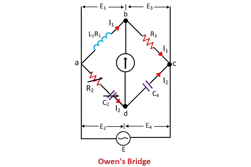
Ang diagrama ng koneksyon ng puente ni Owen, tulad ng ipinapakita sa kasama na larawan, ay nagpapakita ng tiyak na pagkakasunud-sunod ng iba't ibang elektrikal na elemento nito. Ang diagramang ito ay nagbibigay ng visual na gabay upang maintindihan kung paano nakonfigure ang bridge circuit, na binibigyang-diin ang mga interkonseksyon sa pagitan ng inductor na isusubok, ng standard na kapasitor, at iba pang kaugnay na komponente. Sa pamamagitan ng maingat na disenyo na ito, ang puente ni Owen ay nagbibigay-daan para sa tumpak at mapagkakatiwalaang pagsukat ng inductance, kaya ito ay isang mahalagang kasangkapan sa electrical engineering para sa pag-characterize ng mga inductive components.
Puente ni Owen: Konfigurasyon ng Circuit at Balanced State
Sa puente ni Owen, ang circuit ay binubuo ng apat na distinct na arms na may label na ab, bc, cd, at da. Ang arm na ab ay buong inductive, na naglalaman ng hindi alam na inductor L1 na kailangang sukatin. Ang arm na bc, sa kabilang banda, ay may purely resistive na katangian. Ang arm na cd ay may fixed na kapasitor C4, habang ang arm na ad ay naglalaman ng combination ng variable resistor R2 at variable capacitor C2, parehong konektado sa serye sa loob ng circuit.
Ang pundamental na operasyon ng puente ni Owen ay kasama ang paghahambing ng hindi alam na inductor L1 sa arm na ab sa pamamagitan ng kilalang kapasitor C4 sa arm na cd. Upang makamit ang balanced state sa bridge, ang resistor R2 at ang capacitor C2 ay ayusin nang independiyente. Kapag natamo ng bridge ang balansadong kondisyon, ang isang key indicator ay ang walang current na tumatahi sa detector na naka-locate sa pagitan ng points b at c. Ang absence ng current ay nagpapahiwatig na ang endpoints b at c ng detector ay nasa parehong electrical potential, na itinatag ang kinakailangang equilibrium para sa tumpak na pagsukat.
Phasor Diagram ng Puente ni Owen
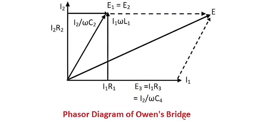
Ang phasor diagram ng puente ni Owen, na ipinapakita sa larawan sa ibaba, ay nagbibigay ng visual na representasyon ng mga electrical quantities at kanilang phase relationships sa loob ng bridge circuit. Ito ay nagbibigay ng mahalagang insights kung paano ang voltages at currents ay nagsasama sa iba't ibang puntos sa circuit, lalo na sa panahon ng balanced state, na nagbibigay-daan para sa mas malalim na pag-unawa sa operational principles ng bridge at sa underlying electrical phenomena.
Phasor Analysis at Theory ng Puente ni Owen
Sa puente ni Owen, ang current I1, kasama ang voltages E3 = I3 R3 at E4=ω I2 C4, lahat ay may parehong phase. Ang mga quantity na ito ay ipinapakita sa horizontal axis ng phasor diagram, na nagpapahiwatig ng kanilang in-phase relationship. Pareho, ang voltage drop I1 R1 sa arm na ab ay din ipinapakita sa horizontal axis, na nagpapahiwatig ng kanilang phase alignment sa iba pang horizontally-oriented phasors.
Ang total na voltage drop E1 sa arm na ab ay ang resulta ng pag-combine ng dalawang components: ang inductive voltage drop ω L1 I1 at ang resistive voltage drop I1 R1. Kapag natamo ng bridge ang balanced state, ang voltages E1 at E2 sa arms ab at ad, respectively, ay naging equal sa magnitude at phase. Bilang resulta, sila ay ipinapakita sa parehong axis sa phasor diagram, na nagpapahiwatig ng equilibrium condition ng bridge circuit.
Ang voltage drop V2 sa arm na ad ay binubuo ng dalawang bahagi: ang resistive voltage drop I2 R2 at ang capacitive voltage drop I2 ω C2. Dahil sa presence ng fixed capacitor C4 sa arm na cd, ang current I2 na tumatahi sa arm na ad ay nangunguna sa voltage drop V4 sa arm na cd ng 90 degrees. Ang phase difference na ito ay isang key characteristic ng capacitive-inductive interaction sa loob ng bridge circuit.
Ang current I2 at ang voltage I2 R2 ay ipinapakita sa vertical axis ng phasor diagram, tulad ng ipinapakita sa figure. Ang supply voltage ng bridge ay nakuha sa pamamagitan ng phasor addition ng voltages V1 at V3, na nag-combine ng electrical contributions mula sa iba't ibang bahagi ng circuit.
Theory ng Puente ni Owen
Let:
At the balance condition of Owen's bridge,
I2 C4, all share the same phase. These quantities are represented along the horizontal axis of the phasor diagram, signifying their in - phase relationship. Similarly, the voltage drop I1 R1 across the arm ab is also plotted on the horizontal axis, reflecting its phase alignment with the other horizontally - oriented phasors.
The total voltage drop E1 across the arm ab is the result of combining two components: the inductive voltage drop ωL1 I1 and the resistive voltage drop I1 R1. When the bridge attains a balanced state, the voltages E1 and E2 across the arms ab and ad, respectively, become equal in magnitude and phase. Consequently, they are depicted on the same axis in the phasor diagram, emphasizing the equilibrium condition of the bridge circuit.
The voltage drop V2 across the arm ad is composed of two parts: the resistive voltage drop I2 R2 and the capacitive voltage drop I2 C2. Due to the presence of the fixed capacitor C4 in the arm cd, the current I2 flowing through the arm ad leads the voltage drop V4 across the arm cd by 90 degrees. This phase difference is a key characteristic of the capacitive - inductive interaction within the bridge circuit.
The current I2 and the voltage I2 R2 are represented on the vertical axis of the phasor diagram, as illustrated in the figure. The supply voltage of the bridge is obtained by the phasor addition of the voltages V1 and V3, which combines the electrical contributions from different parts of the circuit.
Theory of Owen's Bridge
Let:
At the balance condition of Owen's bridge,

On separating the real and imaginary part we get,

And,

Advantages and Disadvantages of Owen's Bridge
Advantages of Owen's Bridge
Owen's bridge offers several notable benefits, making it a valuable tool in electrical measurements:
Disadvantages of Owen's Bridge
Despite its advantages, Owen's bridge also has some limitations:
Modifications to Owen's Bridge
To address some of its inherent limitations or adapt it to different measurement requirements, Owen's bridge can be modified. One common modification involves connecting a voltmeter in parallel with the resistive arms of the bridge. This setup allows for the application of both direct and alternating current supplies to the bridge. An ammeter is connected in series with the bridge to measure the direct current, while the alternating current is measured using the voltmeter. These modifications enhance the bridge's functionality and enable more comprehensive electrical measurements, although they may also introduce additional complexity to the overall circuit setup.
Inirerekomenda


