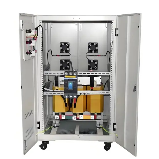
Fault Detection and Maintenance of Power Transformers

Noah
08/28/2025

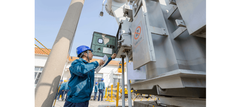
Power transformer fault detection and repair typically require operation by experienced and qualified technical personnel. Below are some common steps for power transformer fault detection and maintenance:

I. Check the transformer’s input and output voltage, current, temperature, and other parameters to ensure they are within normal ranges.

  • Carefully read the transformer’s instruction manual to understand its rated voltage and current, temperature limits, and other special requirements.
  • Use a multimeter to test voltage and current on both the input and output sides of the transformer. During testing, first set the multimeter to an appropriate range, then connect the probes to the transformer’s input and output terminals, and record the voltage and current values.
  • Check the transformer’s temperature. Using a thermometer or infrared thermal imager, measure key components according to the manual or actual conditions. The temperature should be within the allowable range, and temperatures on the input and output sides should be comparable.
  • Inspect the transformer’s insulation condition. Use a multimeter or a dedicated insulation resistance tester to measure the insulation resistance between the windings and ground. Confirm whether the insulation resistance meets the required values as specified in the manual or based on actual conditions.
  • Check the transformer’s oil level, oil quality, and oil temperature. The oil level should be within the normal range, the oil quality should be good, and the oil temperature should be within acceptable limits. Address any abnormalities immediately if detected.

Checking the transformer’s input/output voltage, current, and temperature parameters is crucial for ensuring normal operation and extending the transformer’s service life.

II. Inspect the transformer winding connections for correctness, secure joints, and absence of poor contact.

  • First, review the transformer’s wiring diagram to confirm that connections on both sides comply with standards, including proper cable selection, securely fastened terminals, and correct joint configurations.
  • Examine the wiring box, terminal box, and other connection areas to ensure connections are stable and reliable, joints are secure, and there are no signs of overheating, oxidation, or physical damage.
  • Use tools such as a multimeter to check the winding connections. Test voltage or current transformation to verify correct connections and detect issues like poor contact or short circuits.
  • If possible, perform a power-on test and observe the operational status and changes in electrical parameters to confirm the integrity of wiring and connections.

Appropriate tools and testing methods should be selected based on site conditions, with necessary maintenance and adjustments performed as needed.

III. Inspect the transformer’s cooling system, including fans, water cooling units, and cooling oil, to ensure normal operation.

  • Inspect the fan system: First, verify whether the transformer is equipped with a fan system. If so, check that the fans are operating normally. You can place your hand near the fan inlet to confirm airflow.
  • Inspect the water cooling system: If the transformer uses water cooling, check that the cooling water flows freely and that discharge pipes are not blocked. Inspect from the water inlet of the cooling unit.
  • Inspect the cooling oil: For oil-cooled transformers, check the oil level and oil quality. Add oil if the level is low; replace the oil if its quality has degraded.
  • Inspect the heat sinks: Check the transformer’s heat sinks for dust accumulation or blockages, and clean them if necessary.

Note: Power must be disconnected before inspection to ensure safety.

IV. Inspect external insulation components, such as insulators, bushings, and seals, for damage or defects.

  • Inspect surface insulation materials: Check external insulation materials (e.g., rubber, plastic) for damage, aging, or deterioration. Replace immediately if any issues are found.
  • Inspect support insulator bricks: If the transformer has support insulator bricks, verify they are intact with no cracks or detachment.
  • Check grounding: Ensure the grounding connection between the transformer enclosure and earth is secure and free of looseness.
  • Check labeling: Verify that external labels (e.g., rated voltage, current) are clear, legible, and correctly marked.

During inspection, power must be disconnected and the equipment discharged in advance to ensure safety. Report any issues to qualified technicians immediately.

V. Perform partial discharge (PD) testing to assess the transformer’s partial discharge performance and insulation condition.

Partial discharge testing helps evaluate the transformer’s PD performance and insulation status, enabling early detection and resolution of potential faults. The specific steps are as follows:

  • Preparation: Select appropriate instruments and sensors, and connect and configure them according to instructions.
  • Clean the surface: Clean the transformer’s surface thoroughly to remove dirt and moisture, which could otherwise affect measurement accuracy.
  • Conduct the test: Securely attach sensors to the transformer’s surface and monitor partial discharge signals in real time, ensuring the instrument detects any changes in partial discharge current. Test duration varies based on equipment capacity and required precision, typically ranging from several hours to several days.
  • Analyze results: Analyze the data, compare PD levels at different measurement points, eliminate interference, locate abnormal areas, identify fault causes and severity, and determine whether repair or component replacement is needed.
  • Address faults: If abnormal PD is detected, promptly determine the cause and take corrective actions. Common measures include enhancing insulation, reinforcing local areas, repairing, or adjusting operations to eliminate partial discharge.

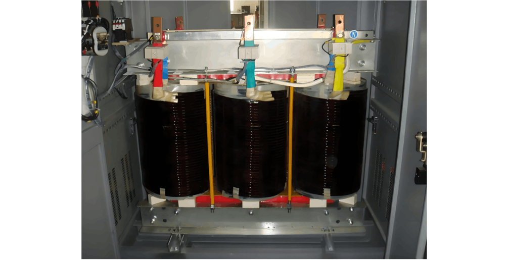
VI. If faults are identified, repair or replace faulty components such as winding coils or insulation materials.

VII. After repairs, perform functional testing to ensure the transformer’s performance meets requirements.

Note: Power transformers are large, high-voltage equipment. Strict adherence to safety procedures during operation is essential to ensure the safety of personnel and equipment.

Noah

Hello, I'm Noah, with nine years of experience in substation design and application. I have extensive engineering design expertise, and I am proficient in primary and secondary systems, electrical layout design, equipment selection, and technical solution development. I also have solid practical knowledge in fault diagnosis, maintenance, and repair of substations, ensuring safe and stable system operation. I am committed to delivering efficient and reliable power system solutions.

Detection, Testing and Comprehensive Monitoring of PV Grid-Connected Cabinets
Photovoltaic (PV) Grid-Connection CabinetA photovoltaic (PV) grid-connection cabinet, also known as a PV grid-connection box or PV AC interface cabinet, is an electrical device used in solar photovoltaic power generation systems. It is primarily responsible for converting the direct current (DC) electricity generated by a PV system into alternating current (AC) and connecting it to the utility grid.Main Components of a PV Grid-Connection Cabinet:DC Input Terminals: Receive DC power generated by
Garca
08/28/2025
Preventive Detection and Testing of Transformers
I. DC Resistance Test of Transformer Primary and Secondary Windings:The DC resistance of transformer primary and secondary windings can be measured using the four-wire (Kelvin) method, which is based on principles related to accurate resistance measurement.In the four-wire method, two test leads are connected to both ends of the winding under test, while the other two leads are connected to adjacent winding terminals. An AC power source is then applied to the two leads connected to the adjacent
Rockwell
08/28/2025
Maintenance, Servicing and Overhaul Key Points for Dry-Type Transformers in Electrical Equipment
I. Key Points for Daily MaintenanceVisual InspectionVisual inspection is the first step during routine patrols. Carefully examine the transformer’s enclosure for any damage or deformation. Enclosure damage not only compromises the transformer’s protective performance but may also expose internal electrical components, increasing safety risks. Additionally, check for dust accumulation, oil stains, or other contaminants on the transformer’s surface. Excessive dust can impair heat
Vziman
08/28/2025
Vulnerable Parts of Transformers and Their Replacement
The vulnerable components of a transformer and their replacement cycles must be determined comprehensively based on factors such as transformer type, operating environment, load conditions, and manufacturing processes.Common Vulnerable Components in Oil-Immersed TransformersOil-immersed transformers rely on insulating oil for heat dissipation and insulation. Their core components include the core, windings, insulation system, cooling system, and accessories. Vulnerable parts are primarily concen
Noah
08/28/2025
Inquiry
Download
IEE-Business is dedicated to serving the personnel in the global power industry.
Join IEE-Business, not only can you discover power equipment and power knowledge, but also canhnd like - minded friends!