Transformer Winding Resistance Testing

Winding Resistance Test Definition
The winding resistance test of a transformer checks the health of transformer windings and connections by measuring resistance.
Purpose of Winding Resistance Test
This test helps in calculating I2R losses, winding temperature, and identifying potential damage or abnormalities.
Measurement Methods
For star connected winding, the resistance shall be measured between the line and neutral terminal.
For star connected autotransformers the resistance of the HV side is measured between HV terminal and HV terminal, then between HV terminal and the neutral.
For delta connected windings, measurement of winding resistance shall be done between pairs of line terminals. As in delta connection the resistance of individual winding can not be measured separately, the resistance per winding shall be calculated as per the following formula:
Resistance per winding = 1.5 × Measured value
The resistance is measured at ambient temperature and converted to resistance at 75°C for comparison with design values, past results, and diagnostics.
Winding Resistance at standard temperature of 75°C

Rt = Winding resistance at temperature t
t = Winding temperature
Bridge Method of Measurement of Winding Resistance
The main principle of the bridge method is based on comparing an unknown resistance with a known resistance. When currents flowing through the arms of the bridge circuit become balanced, the reading of galvanometer shows zero deflection that means at balanced condition no current will flow through the galvanometer.
A very small value of resistance (in milli-ohms range) can be accurately measured by the Kelvin bridge method whereas for higher value Wheatstone bridge method of resistance measurement is applied. In bridge method of measurement of winding resistance, the errors are minimized.
The resistance measured by Kelvin bridge,

The resistance measured by Wheatstone bridge,

Key Considerations and Precautions
Test current should not exceed 15% of the winding’s rated current to avoid heating and changing resistance values.
-
10kV Grade Three-phase Dry-type Grounding Transformer
-
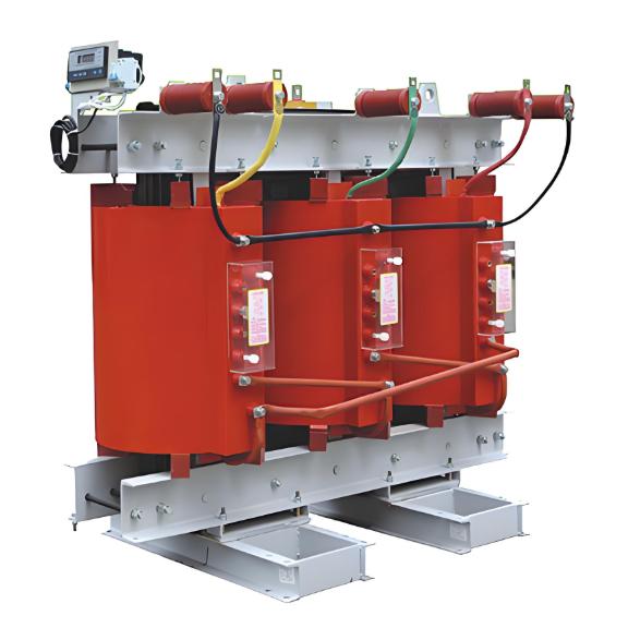
SC Series epoxy casting dry-type transformer

-
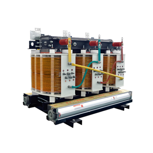
Non-encapsulated H-class Dry-type Power Transformers 800kVA 1000kVA 1250kVA 1600kVA 2000kVA 2500kVA
-
Dry type power transformers 500kVA 1000kVA,35kV dry type distribution transformer,800 kVA dry transformer 3 phase


