Reciprocity Theorem

Rabert T
03/09/2024

The Reciprocity Theorem is a principle in electromagnetics that relates the voltage and current at two points in a linear, passive network. It states that the ratio of the voltage at one point to the current at another point is equal to the ratio of the current at the first point to the voltage at the second point.

WechatIMG1351.jpeg

What is the formula for the reciprocity theorem?

Mathematically, the Reciprocity Theorem can be expressed as:

V1/I1 = V2/I2

where:

V1 – the voltage at the first point

I1 – the current at the first point

V2 – the voltage at the second point

I2 – the current at the second point

The Reciprocity Theorem is based on the idea that the relationships between voltage and current in a linear, passive network are reciprocal. This means that the voltage and current at any two points in the network can be interchanged without affecting the overall behavior of the network.

The Reciprocity Theorem is a useful tool for analyzing and designing electrical circuits and systems, particularly when the circuit or system is symmetrical. It allows engineers to use symmetry to simplify the analysis of the circuit or system, making it easier to understand its behavior and to design it effectively.

The Reciprocity Theorem is only applicable to linear, passive networks. It is not applicable to nonlinear networks or to networks with active elements, such as amplifiers.

Where can see the application of the reciprocity theorem?

Reciprocity theorem is utilised in both

  • Direct current circuits and

  • Alternating current circuits.

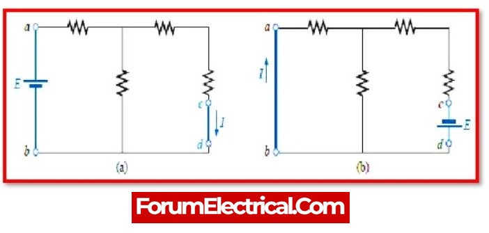
The reciprocity theorem, in layman’s terms, asserts that when the locations of the any network’s voltage and current sources are switched, the same or equal amount of voltage and current flowing through the circuit.

Statement: Respect the original, good articles worth sharing, if there is infringement please contact delete.

Rabert T

As an electrical engineer with 5 years of experience, I focus on transformer and circuit breaker reliability in 110/33-11kV and 33/11kV substations. I am a professional electrical engineer with experience in transformer service and maintenance.

Electrical And Electronic Symbols
An electrical symbol is a small image used to represent an electrical or electronic device or function. They are also known as circuit symbols or schematic symbols as they are used in electrical schematics and diagrams.Some basic electrical symbols include: Wires Diode Batteries Transformers Capacitors Resistors Inductors Fuses Switches Bipolar Junction Transistors Electromagnetic RelaysThere are many electrical and circuit symbols used internationally around the world. While they are mostly st
Blake
03/18/2024
Electrical Transformers – Formulas and Equations
Transformers are one of the most common types of electrical devices, and they may be found in a variety of applications within the area of electrical engineering, including power systems. Therefore, in the position of an electrical engineer, it is usually neededto compute various characteristics of a transformer in order to establish the circumstances under which it operates. In order to do this,will need to use conventional equations, which can be seen mentioned in the sections that will follow
Hobo
03/18/2024
Lenz's Law Explained
Lenz's Law, named after the Russian physicist Heinrich Lenz (1804-1865), is a fundamental principle in electromagnetism. It states that the direction of the induced electromotive force (emf) in a closed conducting loop always opposes the change in magnetic flux that caused it. This means that the induced current creates a magnetic field that opposes the initial change in magnetic flux, following the principles of conservation of energy.Understanding Lenz's Law allows us to appreciate the science
The Electricity Forum
03/18/2024
What is Shunt Resistor and How Does it Work?
In several electrical and power applications, the measurement of current flow is essential.Hence, current measurement is commonly required for monitoring and controlling applications.Depending on the kind of application, many types of current sensors with specialised current sensing technologies are available to detect (or)measure current flow.A current sensing resistor, also known as a shunt resistor, is the most prevalent methodto measure current flow in any application.This postdescribes shun
Rabert T
03/12/2024
Inquiry
Download
IEE-Business is dedicated to serving the personnel in the global power industry.
Join IEE-Business, not only can you discover power equipment and power knowledge, but also canhnd like - minded friends!