Lenz's Law Explained

The Electricity Forum
03/18/2024

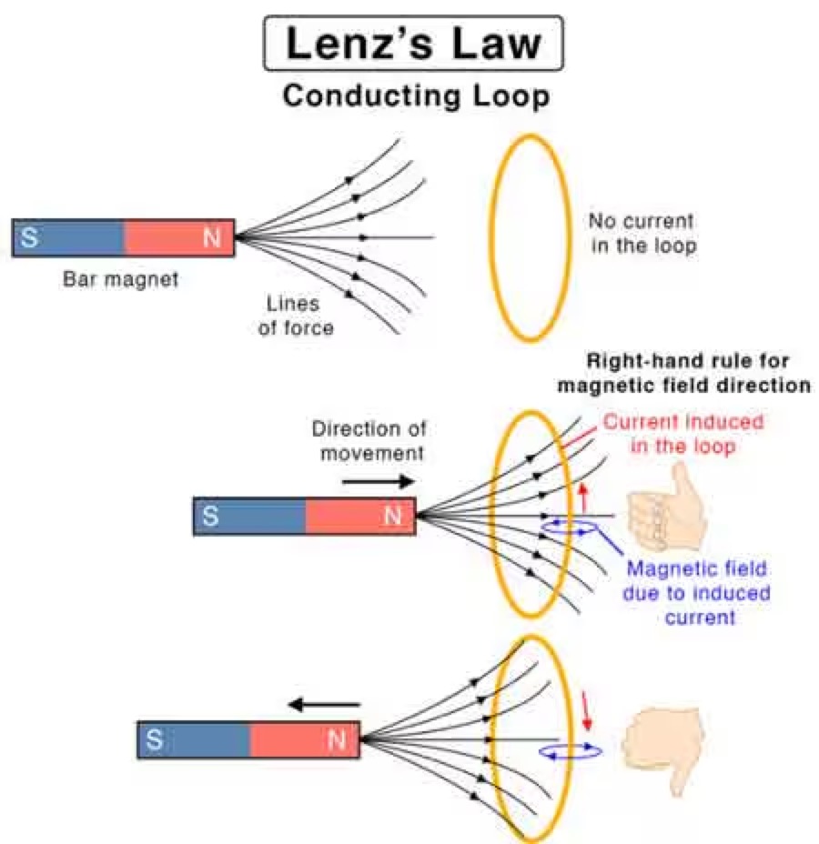
Lenz's Law, named after the Russian physicist Heinrich Lenz (1804-1865), is a fundamental principle in electromagnetism. It states that the direction of the induced electromotive force (emf) in a closed conducting loop always opposes the change in magnetic flux that caused it. This means that the induced current creates a magnetic field that opposes the initial change in magnetic flux, following the principles of conservation of energy.

WechatIMG1558.jpeg 

Understanding Lenz's Law allows us to appreciate the science behind numerous everyday applications, such as electric generators, motors, inductors, and transformers. By delving into the principles of Lenz's Law, we gain insight into the inner workings of the electromagnetic world surrounding us.

Lenz's Law, named after the Russian physicist Heinrich Lenz (1804-1865), is a fundamental principle that governs electromagnetic induction. It states that the induced electromotive force (emf) in a closed conducting loop always opposes the change in magnetic flux that caused it. In simpler terms, the direction of the induced current creates a magnetic field that opposes the initial change in magnetic flux.

Lenz's Law is a fundamental law of electromagnetism that states that the direction of an induced electromotive force (EMF) in a circuit is always such that it opposes the change that produced it. Mathematically, Lenz's Law can be expressed as:

EMF = -dΦ/dt

Where EMF is the electromotive force, Φ is the magnetic flux, and dt is the change in time. The negative sign in the equation indicates that the induced EMF is in the opposite direction to the change in flux.

Lenz's Law is closely related to Faraday's Law of electromagnetic induction, which states that a changing magnetic field induces an EMF in a circuit. Faraday's Law can be expressed mathematically as:

EMF = -dΦ/dt

where EMF is the electromotive force, Φ is the magnetic flux, and dt is the change in time.

Ampere's Law and the Biot-Savart Law are also related to Lenz's Law, as they describe the behaviour of electric and magnetic fields in the presence of currents and charges. Ampere's Law states that the magnetic field around a current-carrying wire is proportional to the current and the distance from the wire. The Biot-Savart Law describes the magnetic field produced by a current-carrying wire or a group of wires.

Together, these laws provide a complete description of the behaviour of electric and magnetic fields in various situations. As a result, they are essential for understanding the operation of electric motors, generators, transformers, and other devices.

To understand it better, consider the scenario of a bar magnet moving toward a coil of wire. When the magnet moves closer to the coil, the magnetic field lines passing through the coil increase. According to Lenz's Law, the polarity of the induced emf in the coil is such that it opposes the increase in magnetic flux. This opposition creates an induced field that opposes the motion of the magnet, ultimately slowing it down. Similarly, when the magnet is moved away from the coil, the induced emf will oppose the decrease in magnetic flux, creating an induced field that will try to keep the magnet in place.

The induced field that opposes the change in magnetic flux follows the right-hand rule. If we hold our right hand around the coil such that our fingers point in the direction of the magnetic field lines, our thumb will point in the direction of the induced current. The direction of the induced current is such that it creates a magnetic field that opposes the change in the magnetic flux.

The pole of the magnet also plays a crucial role in Lenz's Law. When the magnet's north pole moves towards the coil, the induced current creates a magnetic field that opposes the north pole's approach. Conversely, when the magnet's south pole moves towards the coil, the induced current creates a magnetic field that opposes the south pole's approach. The direction of the induced current follows the right-hand rule, as we discussed earlier.

It is related to Faraday's Law of electromagnetic induction, which explains how a changing magnetic field can induce an emf in a conductor. Faraday's Law mathematically describes the relationship between the induced emf and the magnetic flux rate of change. It follows Faraday's Law, as it governs the direction of the induced emf in response to the changing magnetic flux.

It is also related to the phenomenon of eddy currents. Eddy currents are loops of electric current induced within conductors by a changing magnetic field. The circulating flow of these currents generates their magnetic field, which opposes the initial magnetic field that created them. This effect is in line with Lenz's Law and has practical applications, such as in the braking systems of trains and induction cooktops.

It has numerous practical applications in our daily lives. For example, it plays a significant role in the design and function of electric generators, which convert mechanical energy into electrical energy. In a generator, a rotating coil experiences a changing magnetic field, leading to the generation of an emf. The direction of this induced emf is determined by Lenz's Law, which ensures that the system conserves energy. Similarly, electric motors operate based on Lenz's Law. In an electric motor, the interaction between the magnetic fields and the induced emf creates a torque that drives the motor.

It is an essential concept in the design of inductors and transformers. Inductors are electronic components that store energy in their magnetic field when a current flows through them. They oppose any change in the current, following the principles of Lenz's Law. Transformers, which are used to transfer electrical energy between circuits, utilize the phenomenon of electromagnetic induction. By understanding it, engineers can design transformers.

Statement: Respect the original, good articles worth sharing, if there is infringement please contact delete.

The Electricity Forum

Electricity Forum publishes Electricity Today T&D Magazine and Intelligent Power Today Industrial Electrical Magazine. We publish electrical technical handbooks and associated digital magazine advertising supplements.

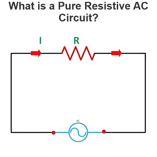
What is a Pure Resistive AC Circuit?
Pure Resistive AC CircuitA circuit containing only a pure resistanceR(in ohms) in an AC system is defined as a Pure Resistive AC Circuit, devoid of inductance and capacitance. Alternating current and voltage in such a circuit oscillate bidirectionally, generating a sine wave (sinusoidal waveform). In this configuration, power is dissipated by the resistor, with voltage and current in perfect phase—both reaching their peak values simultaneously. As a passive component, the resistor neither
Edwiin
06/02/2025
What is a Pure Capacitor Circuit?
Pure Capacitor CircuitA circuit comprising only a pure capacitor with capacitanceC(measured in farads) is termed a Pure Capacitor Circuit. Capacitors store electrical energy within an electric field, a characteristic known ascapacitance(alternatively referred to as a "condenser"). Structurally, a capacitor consists of two conductive plates separated by a dielectric medium—common dielectric materials include glass, paper, mica, and oxide layers. In an ideal AC capacitor circuit, the current
Edwiin
06/02/2025
Resistance Switching in a Circuit Breaker
Resistance SwitchingResistance switching refers to the practice of connecting a fixed resistor in parallel with the contact gap or arc of a circuit breaker. This technique is applied in circuit breakers with high post-arc resistance in the contact space, primarily to mitigate re-striking voltages and transient voltage surges.Severe voltage fluctuations in power systems arise from two main scenarios: interrupting low-magnitude inductive currents and breaking capacitive currents. Such overvoltages
Edwiin
05/23/2025
What is Biot Savart Law?
The Biot-Savart Law is employed to determine the magnetic field intensity dHnear a current-carrying conductor. In other words, it describes the relationship between the magnetic field intensity generated by a source current element. This law was formulated in 1820 by Jean-Baptiste Biot and Félix Savart. For a straight wire, the direction of the magnetic field adheres to the right-hand rule. The Biot-Savart Law is also referred to as Laplace’s law or Ampère’s law.Conside
Edwiin
05/20/2025
Inquiry
Download
IEE-Business is dedicated to serving the personnel in the global power industry.
Join IEE-Business, not only can you discover power equipment and power knowledge, but also canhnd like - minded friends!