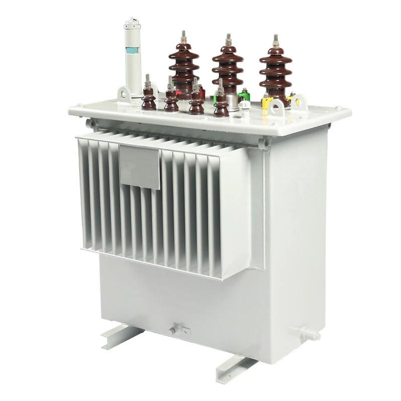
Evaluation and Analysis of Load Characteristics of Distribution Transformers

04/14/2025

In-depth Analysis and Key Considerations for Load Characteristic Evaluation

Load characteristic evaluation is a cornerstone of distribution transformer design, directly influencing capacity selection, loss distribution, temperature rise control, and operational economy. The evaluation must be conducted across three dimensions: load type, temporal dynamics, and environmental coupling, with a refined model established based on actual operating conditions.

1. Refined Analysis of Load Types

  • Classification and Characteristics
    • Residential Loads: Dominated by lighting and household appliances, with a daily load curve exhibiting dual peaks (morning and evening) and a low annual load factor (approximately 30%–40%).
    • Industrial Loads: Categorized into continuous (e.g., steel mills), intermittent (e.g., machining), and impact loads (e.g., electric arc furnaces), requiring attention to harmonics, voltage fluctuations, and inrush currents.
    • Commercial Loads: Such as shopping malls and data centers, characterized by seasonal variations (e.g., summer air conditioning) and nonlinear characteristics (e.g., UPS, frequency converters).
  • Load Modeling
    • Employ equivalent circuit models or measured data fitting to quantify power factor (PF), harmonic content (e.g., THDi), and load rate fluctuations.

2. Dynamic Analysis Across Temporal Dimensions

  • Daily Load Curve
    • Derived from field monitoring or standard curves (e.g., IEEE), highlighting peak and off-peak periods and their durations.
    • Example: An industrial park’s daily curve reveals dual peaks from 10:00–12:00 and 18:00–20:00, with nighttime load rates below 20%.
  • Annual Load Curve
    • Accounts for seasonal variations (e.g., summer cooling, winter heating) and predicts future load growth using historical data.
    • Key Metrics: Annual maximum load utilization hours (Tmax), load factor (LF), and load coefficient (LF%).

3. Environmental Coupling and Correlation Assessment

  • Temperature Impact
    • Every 10°C increase in ambient temperature reduces transformer rated capacity by approximately 5% (based on thermal aging models), necessitating overloading capability verification.
  • Altitude Impact
    • Every 300m increase in altitude decreases insulation strength by ~1%, requiring insulation design adjustments or capacity derating.
  • Pollution Severity
    • Categorized per IEC 60815 (e.g., light, heavy pollution), influencing bushing and insulator selection and creepage distance.

4. Evaluation Methods and Tools

  • Measurement-Based Approach
    • Collects real-world load data via smart meters and oscillographs, followed by statistical analysis (e.g., load rate distribution, harmonic spectrum).
  • Simulation-Based Approach
    • Utilizes software like ETAP or DIgSILENT to model power systems under various scenarios.
  • Empirical Formulas
    • Such as the load factor formula in IEC 60076 for rapid transformer capacity estimation.

5. Application of Evaluation Results

  • Capacity Selection
    • Determines transformer capacity based on load rate (e.g., 80% design margin) and overloading capability (e.g., 1.5× rated current for 2 hours).
  • Loss Distribution
    • Iron losses (PFe) are load-independent, while copper losses (PCu) scale with load squared, necessitating a balance between no-load and load losses.
  • Temperature Rise Control
    • Calculates winding hot-spot temperatures based on load characteristics to ensure compliance with insulation material thermal ratings (e.g., Class A ≤105°C).

Conclusion

Load characteristic evaluation must integrate load type, temporal dynamics, and environmental coupling using measurement, simulation, and empirical methods to build a refined model. The results directly impact capacity selection, loss distribution, and operational reliability, forming the foundation of distribution transformer design.

  • Economic Analysis
    • Compares investment returns of different capacities via life-cycle cost (LCC) assessment.

Hello,I'm Wdwiin. A decade of hands-on experience in electrical engineering, specializing in high-voltage systems, smart grids, and renewable energy technologies. Passionate about technical exchange and knowledge sharing, committed to interpreting industry trends with professional insights to empower peers. Connection creates value—let’s explore the boundless possibilities of the electrical world together!

Research on Bridge-Type Fault Current Limiters
1 Bridge-Type Superconducting Fault Current Limiter1.1 Structure and Operating Principle of the Bridge-Type SFCLFigure 1 shows the single-phase circuit diagram of the bridge-type SFCL, which consists of four diodes D₁ to D₄, a DC bias voltage source V_b, and a superconducting coil L. A circuit breaker CB is connected in series with the limiter to interrupt the fault current after it has been limited. The bias source V_b provides a bias current i_b to the superconducting coil L. The voltage of V_
08/25/2025
What should be paid attention to in the design of low-voltage pole-mounted circuit breakers?
Low-voltage pole-mounted circuit breakers are critical protective and control devices in power systems, whose design and operation directly affect system safety and reliability. Their design must comprehensively address environmental adaptability, electrical parameter coordination, and actuator selection to ensure stable operation under diverse conditions. During operation, strict adherence to safety protocols, regular maintenance, and proper handling of exceptional situations are essential to p
08/21/2025
Study on Steep - Wave Breakdown Characteristics of Hybrid Porcelain Insulators
Porcelain and glass insulators exhibit excellent insulation performance and mechanical strength, but are prone to pollution flashover under severe contamination, threatening the stable operation of power grids. To enhance the pollution flashover resistance of external insulation, manufacturers commonly apply room-temperature vulcanized silicone rubber (RTV) coatings with superior hydrophobicity and hydrophobicity transfer properties onto insulator surfaces, thereby reducing flashover risks. Init
08/20/2025
Research on Energy - Saving Effect of Inverter Speed Regulation Technology in Electrical Automation
As the core of industrial production, electrical automation systems directly influence overall production costs and environmental impact. Traditional constant-speed operation often leads to energy waste when responding to varying load demands and makes precise process control difficult to achieve. Variable frequency speed regulation technology, as an advanced motor control method, offers a promising solution to these issues. This study takes the electrical automation system of a power plant as a
08/18/2025
Inquiry
Download
IEE-Business is dedicated to serving the personnel in the global power industry.
Join IEE-Business, not only can you discover power equipment and power knowledge, but also canhnd like - minded friends!