
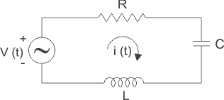
Ang series RLC circuit usa ka resistor, inductor ug capacitor nga giconnect sa series sa usa ka voltage supply. Ang resulta nga circuit gitawag og series RLC circuit. Usa ka circuit ug phasor diagram alang sa series RLS circuit gitun-an sa ubos.
Ang phasor diagram sa series RLC circuit gi-construct pinaagi sa pag-combine sa phasor diagram sa resistor, inductor ug capacitor. Bago mibuhat, ang usa ka kahimsog dapat mosabot sa relasyon tali sa voltage ug current sa kasong resistor, capacitor ug inductor.
Resistor
Sa kasong resistor, ang voltage ug current adunay sama nga phase o mahimong masulti nga ang phase angle difference tali sa voltage ug current zero.
Inductor
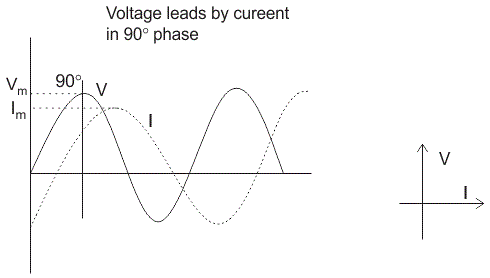
Sa inductor, ang voltage ug current dili adunay sama nga phase. Ang voltage lead sa current sa 90° o sa uban nga pulong, ang voltage nagsugyot sa iyang maximum ug zero value 90° sa unang ang current nagsugyot sa iyang maximum ug zero value.
Capacitor
Sa kasong capacitor, ang current lead sa voltage sa 90° o sa uban nga pulong, ang voltage nagsugyot sa iyang maximum ug zero value 0° human sa current nagsugyot sa iyang maximum ug zero value i.e. ang phasor diagram sa capacitor eksakto ang opposite sa inductor.
NOTE: Para molihok sa phase relationship tali sa voltage ug current, basaha ang simple nga pulong nga 'CIVIL', i.e. sa capacitor ang current lead sa voltage ug voltage lead sa current sa inductor.![]()
RLC Circuit
Para sa pagdraw sa phasor diagram sa series RLC circuit, sundon ang mga steps:
Step – I. Sa kasong series RLC circuit; ang resistor, capacitor ug inductor giconnect sa series; busa, ang current nga nagflow sa tanang elemento sama i.e. I r = Il = Ic = I. Para sa pagdraw sa phasor diagram, huna-huna ang current phasor isip reference ug draw kini sa horizontal axis sama sa diagram.
Step – II. Sa kasong resistor, ang duha ka voltage ug current adunay sama nga phase. Busa, draw ang voltage phasor, VR sa sama nga axis o direction sama sa current phasor i.e. VR adunay sama nga phase sa I.
Step – III. Alam nato nga sa inductor, ang voltage lead sa current sa 90° busa draw Vl (voltage drop across inductor) perpendicular sa current phasor sa leading direction.
Step – IV. Sa kasong capacitor, ang voltage lags behind sa current sa 90° busa draw Vc (voltage drop across capacitor) perpendicular sa current phasor sa downwards direction.
Step – V. Para sa pagdraw sa resultant diagram, draw Vc sa upwards direction. Tuman-an ang resultant, Vs nga vector sum sa voltage Vr ug VL – VC.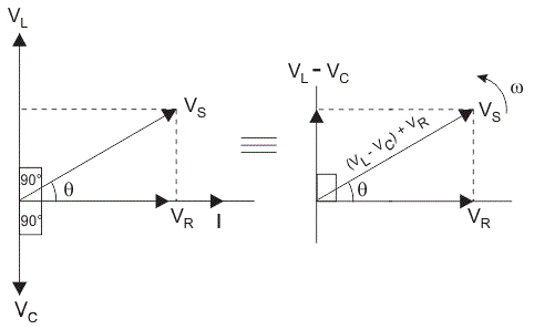
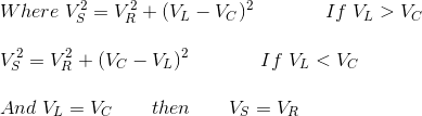
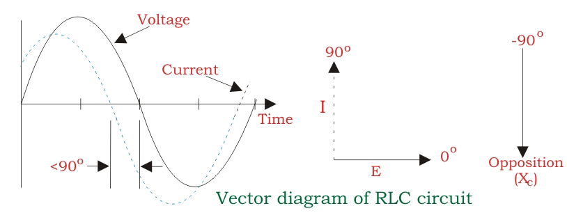
Ang impedance Z sa series RLC circuit gidefine isip opposition sa flow sa current, tungod sa circuit resistance R, inductive reactance, XL ug capacitive reactance, XC. Kon ang inductive reactance mas dako sa capacitive reactance, i.e XL > XC, ang RLC circuit adunay lagging phase angle ug kon ang capacitive reactance mas dako sa inductive reactance, i.e XC > XL ang RLC circuit adunay leading phase angle ug kon parehas ang inductive ug capacitive, i.e XL = XC ang circuit moguba isip purely resistive circuit.
Alam nato nga,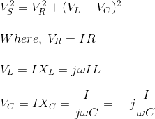
Substituting the values VS2 = (IR)2 + (I XL – I XC )2![]()
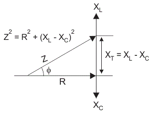
From this impedance triangle: by using Pythagoras theorem we get;


