Analysis of Two 10kV SF₆ Ring Main Unit Failures and Live Testing

Analysis of Two 10kV SF₆ Ring Main Unit Failures and Live Testing
1 Introduction to 10kV SF₆ Ring Main Units
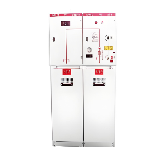
A 10kV SF₆ ring main unit (RMU) typically consists of a gas tank, an operating mechanism compartment, and a cable connection compartment.
- Gas Tank: The most critical component, housing the load switch busbar, switch shaft, and SF₆ gas. The load switch is a three-position switch, including an isolating blade and an arc-extinguishing shield.
- Operating Mechanism Compartment: The operating mechanism connects to the load switch and grounding switch via the switch shaft. Operators insert an operating rod into the access hole to perform closing, opening, or grounding operations. Since switch contacts are not visible, a position indicator directly linked to the shaft clearly displays the current status of the load and grounding switches. Mechanical interlocks between the load switch, grounding switch, and front panel ensure compliance with the "five preventions" safety requirements.
- Cable Connection Compartment: Located at the front of the RMU for easy cable connection. Cable terminations use touchable or non-touchable live silicone rubber cable accessories to connect to the RMU’s insulating bushings.
2 Analysis of Two Failures
2.1 SF₆ Gas Leakage Failure
A 10kV line outage occurred due to a fault. Inspection revealed smoke emitting from a Yangmeikeng RMU. After opening the cabinet, the #2 switch cable terminal was found fractured, with gas leaking from the tank. Removal of the elbow connector showed that the double-ended stud for bushing installation was not centered in the lug hole, causing prolonged downward force on the bushing and leading to cracking at the root.
Such failures often occur at cable terminals due to improper installation, resulting in sustained stress that cracks the gas tank-to-terminal interface and SF₆ leakage. Alternatively, poor manufacturing seals may cause leaks.
2.2 Cable Termination Failure in RMU
During routine inspection, a 10kV RMU cabinet door appeared blackened, indicating possible discharge. The four-unit RMU’s fourth unit was spare. Post-outage inspection revealed significant discharge in the second and third units:
- Unit 2: Phase C stress cone showed discharge marks and blackening on the cabinet wall.
- Unit 3: Phase B cable elbow exhibited discharge burns.
Disassembly revealed: - Unit 2: The stress cone was installed too low, entirely below the cable semiconductive break. Poor contact at both ends caused electric field concentration, leading to breakdown and discharge against the cabinet.
- Unit 3: An incorrect outdoor cable lug (smaller size) was used instead of the original. Spacers were illegally inserted between the lug and bushing copper core, causing poor contact and overheating. An oversized elbow failed to seal the stress cone, allowing moisture ingress, insulation degradation, and tracking.
Cable termination quality is crucial in compact RMUs. Substandard conductor, shielding, or semiconductive layer treatment reduces creepage distance, risking breakdown. Strict quality control during termination minimizes failure risks.
3 Live Testing Analysis
3.1 Live Testing Findings
In October, partial discharge (PD) testing on 10kV RMUs detected abnormally high signals (TEV ≈18dB, AE ≈20dB) in units from one manufacturer. Subsequent tests on 15 units revealed similar discharges in 7. Observation windows showed tracking marks on cable terminations, with T-heads exhibiting burns. Disassembly confirmed severe discharge damage:
- Surfaces of plugs, surge arresters, epoxy bushings, and seals showed tracking burns.
- Loose interfaces between plugs and seals allowed moisture ingress, corroding metal parts and degrading insulation.
After replacing components, PD levels returned to normal.
3.2 Testing Methodology Summary
PD assessment combines "listening," "smelling," "observing," and "testing":
- Preparation: Verify equipment safety, calibrate PD instruments, and cross-check system IDs.
- Preliminary Checks:
- Monitor gas pressure.
- Listen for abnormal sounds (if present, evacuate and report).
- Smell for burnt odors before opening doors.
- Visually inspect via windows: tree-like discharge traces on T-heads or white melting on insulation plugs indicate faults.
- Testing Procedure:
① Measure background TEV on non-energized metal doors to gauge overall PD levels.
② TEV testing: Press sensors firmly against metal doors; locate PD sources by signal attenuation.
③ AE testing: Scan door gaps. - Result Criteria (Shenzhen Utility Standard):
|
Result |
TEV (dB) |
AE (dB) |
|
Normal |
≤15 |
≤10 |
|
Minor PD |
15–25 |
10–20 |
|
Moderate PD |
25–35 |
20–30 |
|
Severe PD |
≥35 |
≥30 |
4 Conclusion
Key insights:
① SF₆ RMUs are increasingly deployed at critical nodes in distribution networks due to their advantages.
② 10kV SF₆ RMU failures often stem from poor cable termination craftsmanship. Rigorous quality control, on-site supervision, and pre-commissioning tests are essential to reduce faults.
③ Live PD testing enables non-disruptive health assessments, facilitating defect mitigation and minimizing outage risks.