• UniGear ZS1  Air-insulated switchgear for power application
UniGear ZS1 Air-insulated switchgear for power application
discuss personally
Model
UniGear ZS1-17.5
UniGear ZS1-24
UniGear ZS1-12
Basic info
Brand ABB
Model NO. UniGear ZS1 Air-insulated switchgear for power application
Rated voltage 17.5kV
Rated frequency 50/60Hz
Series UniGear ZS1
Product Detail

Description:

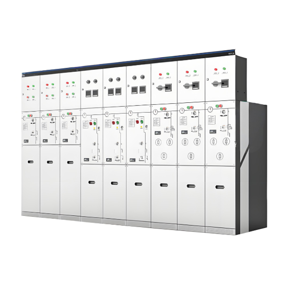
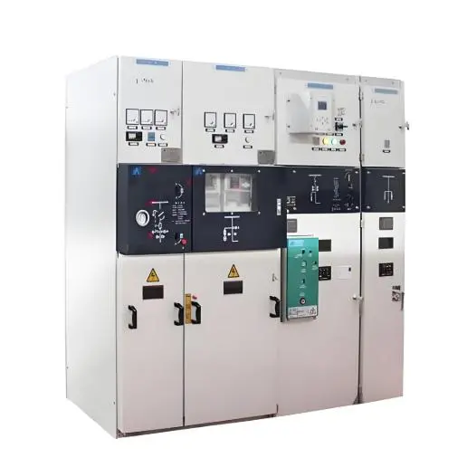
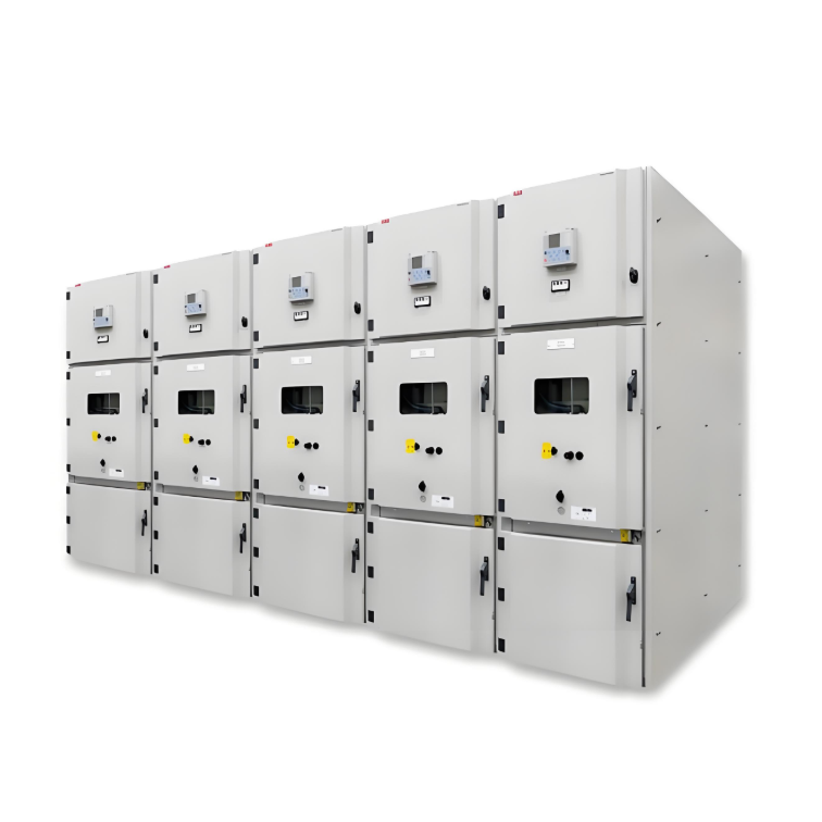
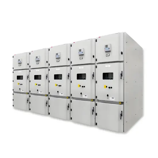
UniGear ZS1 is the ABB mainlineglobal switchgear for primary distribution up to 24 kV, 4 000 A,63 kA.The switchgear is manufacturedworldwide and there are more than 700 000 panels currently installed.

UniGear ZS1 is used to distribute electric power in a variety of demanding applications such as on off shore platforms, in container or cruise ships, in mines as well as in utility substations, power plants or chemical plants.UniGear ZS1 is available as a single busbar, double busbar, back to back or double level solution.

Features

  • Standards: IEC, CSA, GOST, GB/DL.
  • Most of panels classified as LSC2B, PM *.
  • Accessibility type: A.
  • Internal arc class: FLR.
  • Highly customized versions available.
  • Switchgear can be back to wall installed.

Safety

  • Fully type tested according to IEC 62271-200.
  • Fitted with safety interlocks.
  • Circuit breaker racking with closed doors.

UniGear ZS1 panel variants have the most common classification LSC2B, PM. Check other panel variants and their LSC classification in catalogue 1VCP000138.

Switching devices

  • Vacuum circuit breaker with spring actuator.
  • Vacuum circuit breaker with magnetic actuator.
  • SF6 circuit breaker with spring actuator.
  • Vacuum contactor.
  • Switch disconnector.

Current and voltage measurement:

  • Current and voltage sensors.
  • Conventional current and voltage instrument transformers .

Protection and control:

  • Relion® protection and control relays.

Optionally available with:

  • Optical arc fault protection 
  • Ultra Fast Earthing Switch UFES
  • Surge arresters
  • Is-limiter, advanced fault current limiter
  • Smart solutions

Technical parameters

 1.With installed gas exhaust duct 2.Depending on rated feeder current  3. 2 089 – 2 154 mm for 63 kA 4) 42 kV (63 kA version; GB/DL)
 Note: 1 250 A - 40 kA  available at 650 mm panel

Structure diagram

Know your supplier
ABB
As an authorized distributor of ABB products, we take great pride in our partnership.
Main Categories
High voltage/Low voltage
Business Type
Sales
Highest Annual Export (USD)
$580000000
Professional Experience
11 years
Workplace
20000m²
占位
占位
Documents
Public.
UniGear ZS1 Air-insulated switchgear for power application
White paper English
PDF
FAQ
Q: What are the key features of ABB’s medium voltage switchgear products?
A:
ABB‘s primary medium voltage switchgear products are designed to connect and protect the evolving grid. They feature robust construction, advanced safety mechanisms, high reliability, and ease of maintenance. They are designed to handle high electrical loads and provide efficient power distribution with minimal losses.
Q: What standards and certifications that ABB’s medium voltage switchgear products comply with?
A:
Our medium voltage switchgear products comply with international standards such as IEC 62271, GOST, GB/DL. They are also certified by leading industry bodies to ensure the highest levels of safety and performance. ABB also offers medium voltage switchgear products for ANSI standards.
Related Products
Related Knowledges
What are the typical connection methods for 35kV distribution lines?
Typical Wiring Diagram of 35kV Line Radial π ConnectionWhen a 35kV line adopts a radial power grid structure, a single - side power supply or a double - side power supply radial type can be used according to the situation of the power supply points, and a loop - out interval is reserved at the end of the line.Typical Wiring Diagram of 35kV Line Radial T - ConnectionFor double - radial lines, it is advisable to select a double - side power supply. When the power supply points do not meet the r
Leon
07/18/2025
Why are the ground fault point and the accident point not at the same location?
Fault Transfer VoltageIn low - voltage distribution systems, there is a type of personal electric shock accident where the accident occurrence point and the system fault point are not at the same location. This kind of accident occurs because after a ground fault happens elsewhere, the generated fault voltage is conducted to the metal casings of other equipment through the PE wire or PEN wire. When the fault voltage on the metal casing of the equipment is higher than the human - body safe voltag
Leon
07/18/2025
Analysis of Transformer Capacity, Load Rate and Number of Units Selection Issues
The safe and economical operation of power transformers is related to the safety, economy, stability, and reliability of the operations of various industries. The limitations of conditions such as the investment economic indicators for its selection, the economic benefits of maintenance and operation, and the adaptability in the new environment (access of distributed power sources, configuration of energy storage, etc.) make it impossible to include comprehensive factors in other aspects.The cap
Leon
07/17/2025
Analysis of the Impact of Immersion on the Performance of Low-Voltage Current Transformers
1 IntroductionLow - voltage current transformers for metering, with a through - core type epoxy resin structure, are widely used in distribution transformer areas and for small - to - medium - sized industrial and commercial electricity consumption. As a range expander for electric energy metering, their performance directly relates to electricity consumption safety and the accuracy of users' trade calculations. Studying long - term immersion's impact on these transformers is practically signifi
Felix Spark
07/17/2025
What is reactive power measurement?
The power which exists in the circuit when the voltage and current are out of phase to each other, such type of power is known as the reactive power. The formula measures the reactive power in the circuitReactive Power Measurement & VarmetersReactive power measurement is critical as it indicates circuit power loss: low reactive power worsens load power factor, increasing system losses. Varmeters (volt-ampere reactive meters) measure reactive power and are categorized by circuit phases:Single
Edwiin
07/17/2025
How to Design and Install a Solar PV System?
Design and Installation of Solar PV SystemsModern society relies on energy for daily needs like industry, heating, transport, and agriculture, mostly met by non-renewable sources (coal, oil, gas). However, these cause environmental harm, are unevenly distributed, and face price volatility due to limited reserves—driving demand for renewable energy.Solar energy, abundant and capable of meeting global needs, stands out. Standalone PV systems (Fig 1) offer energy independence from utilities.
Edwiin
07/17/2025
×
Inquiry
Download
IEE-Business is dedicated to serving the personnel in the global power industry.
Join IEE-Business, not only can you discover power equipment and power knowledge, but also canhnd like - minded friends!