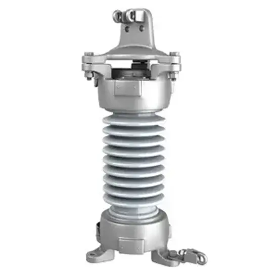
High Voltage Current-Limiting Fuse(For motor protection)


Key attributes
| Brand | Wone |
| Model NO. | High Voltage Current-Limiting Fuse(For motor protection) |
| Rated voltage | 7.2kV |
| Rated normal current | 100A |
| Breaking capacity | 63kA |
| Series | Current-Limiting Fuse |
Product descriptions from the supplier
Characteristic brief :
Rated voltage from 3.6KV to 12KV.
Wide range of rated current from 31,5A to 400A.
BS type and DIN type are all available.
Powerful pyrotechnic or spnng striker.
H.R.C.
Current-limiting.
Low power dissipation, low temperature rise.
Operation extremely quickly, high reliability.
With motor circuit in senes.
Isolating & protecting motor.
Conforming to stanaards: GB15166.2 DIN43625 BS2692-1 IEC60282-1.
Model illustration:

Technical Parameters:

Fuse base table:

External&installation dimensions(Unit:tmm)

BS Type XRNM1 single fuse link

BS Type XRNM1 double fuse link

BS Type XRNM1 three fuse link

DIN Type XRNM2
How does a high-voltage current-limiting fuse (for motor protection) work?
Normal State:
During normal operation of the motor, the high-voltage current-limiting fuse has very low resistance, allowing the normal operating current to pass through without significantly affecting the motor circuit. It behaves like a well-conducting conductor.
Fault Protection:
When an overload or short-circuit fault occurs in the motor, causing the current to exceed the rated current of the fuse, the fusible element rapidly heats up due to the thermal effect of the current. Given the large magnitude of the fault current, the fusible element quickly reaches its melting point and melts, generating an arc.
At this point, the arc-quenching system, which includes materials such as quartz sand, absorbs the heat from the arc, causing it to extinguish rapidly. During this process, the fuse limits the peak value of the fault current, preventing the motor from experiencing excessive current surges.

Related Products
-
Underground Arresters

-
3 to 48kV Porcelain Housed Surge Arresters
-
160 to 500kV High Strength Polymer Housed Surge Arresters

-
24 to 550kV Polymer Housed Surge Arresters

-
36 to 420kV Polymer Housed Surge Arresters

-
12 to 420kVPorcelain Housed Surge Arresters

-
36 to 420kV Live Tank Porcelain Housed Surge Arresters

Related Knowledges
-
 Main Transformer Accidents and Light Gas Operation Issues1. Accident Record (March 19, 2019)At 16:13 on March 19, 2019, the monitoring background reported a light gas action of No. 3 main transformer. In accordance with the Code for Operation of Power Transformers (DL/T572-2010), operation and maintenance (O&M) personnel inspected the on-site condition of No. 3 main transformer.On-site confirmation: The WBH non-electrical protection panel of No. 3 main transformer reported a Phase B light gas action of the transformer body, and the reset was ineff02/05/2026
 -
 Faults and Handling of Single-phase Grounding in 10kV Distribution LinesCharacteristics and Detection Devices for Single-Phase Ground Faults1. Characteristics of Single-Phase Ground FaultsCentral Alarm Signals:The warning bell rings, and the indicator lamp labeled “Ground Fault on [X] kV Bus Section [Y]” illuminates. In systems with a Petersen coil (arc suppression coil) grounding the neutral point, the “Petersen Coil Operated” indicator also lights up.Insulation Monitoring Voltmeter Indications:The voltage of the faulted phase decreases (in01/30/2026
 -
 Neutral point grounding operation mode for 110kV~220kV power grid transformersThe arrangement of neutral point grounding operation modes for 110kV~220kV power grid transformers shall meet the insulation withstand requirements of transformer neutral points, and shall also strive to keep the zero-sequence impedance of substations basically unchanged, while ensuring that the zero-sequence comprehensive impedance at any short-circuit point in the system does not exceed three times the positive-sequence comprehensive impedance.For 220kV and 110kV transformers in new constructi01/29/2026
 -
 Why Do Substations Use Stones, Gravel, Pebbles, and Crushed Rock?Why Do Substations Use Stones, Gravel, Pebbles, and Crushed Rock?In substations, equipment such as power and distribution transformers, transmission lines, voltage transformers, current transformers, and disconnect switches all require grounding. Beyond grounding, we will now explore in depth why gravel and crushed stone are commonly used in substations. Though they appear ordinary, these stones play a critical safety and functional role.In substation grounding design—especially when multiple gr01/29/2026
 -
 Why Must a Transformer Core Be Grounded at Only One Point? Isn't Multi-Point Grounding More Reliable?Why Does the Transformer Core Need to Be Grounded?During operation, the transformer core, along with the metal structures, parts, and components that fix the core and windings, are all situated in a strong electric field. Under the influence of this electric field, they acquire a relatively high potential with respect to ground. If the core is not grounded, a potential difference will exist between the core and the grounded clamping structures and tank, which may lead to intermittent discharge.I01/29/2026
 -
 Understanding Transformer Neutral GroundingI. What is a Neutral Point?In transformers and generators, the neutral point is a specific point in the winding where the absolute voltage between this point and each external terminal is equal. In the diagram below, pointOrepresents the neutral point.II. Why Does the Neutral Point Need Grounding?The electrical connection method between the neutral point and earth in a three-phase AC power system is called theneutral grounding method. This grounding method directly affects:The safety, reliabilit01/29/2026


