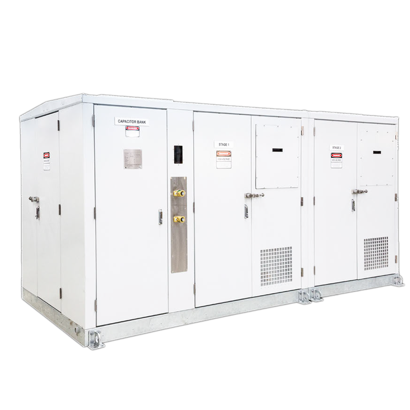
Dynacomp

Key attributes
| Brand | ROCKWILL |
| Model NO. | Dynacomp |
| Rated voltage | 400V |
| Rated capacity | 100kVA |
| Series | Dynacomp |
Product descriptions from the supplier
Overview
Dynacomp principle
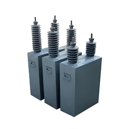
The Dynacomp is a circuit consisting of capacitors and reactors switched on the network by solid state power electronics, without any moving part. A three-phase Dynacomp circuit is represented below. Single-phase
Dynacomps are also available. The Dynacomp can compensate low voltage equipment for nominal voltages from 380V up to 690V.
The thyristors are fired at the natural zero crossing of the capacitive current. As a result, capacitors are connected to the network without transients.
The control is such that only complete cycles of the current are allowed. This ensures that no harmonics or transients are generated by the Dynacomp.
Connection diagram
● This connection is valid for closed-loop and/or external trigger control systems. For other configurations, please consult us. Measurements provided by the controller are network measurements in any case
● Single-phase systems are also available. Please consult us
● External trigger system, if needed, is made through one or two inputs (opto1 and opto2: 15-24Vdc)
Typical applications
Harbour crane
Switching of charged capacitors result in large transients when the capacitor and network voltages are in phase opposition at the closing instant. This is why conventional banks always have delays (~1 minute) between switching on/off the capacitors. This delay permits the discharge of the capacitors through discharge resistors, but limits the utilisation of conventional capacitor banks for rapidly fluctuating loads requiring frequent switchings.
As the switching of the Dynacomp does not require the discharge of the capacitors, the utilisation of the Dynacomp for the compensation of any load with rapid variations is possible. During its cycle, a crane requires variable amounts of reactive power. The whole crane cycle lasts about one minute. Compensation with conventional banks is not possible for this operation: the cycle is too short and the required reactive power is too large. The Dynacomp improves the power factor by reducing the reactive current drawn from the grid. This also results in reduced current drawn from the supply system. The presence of 7% detuning reactor helps in harmonic absorption which is reflected in reduced THDV levels.
Welding machine
Welding equipment typically draws high welding current for a very short time. As a result, the repetitive impermissible voltage variations may result.
In the figures below, 4 steps of 150 kvar are switched on for the compensation of a 210 kVA single phase welder with the use of an external signal for instantaneous response time (voltage drop compensation). These figures show clearly that the voltage drop due to the welding machine is totally reduced. Perturbation to sensitive devices like PLC, computers, lighting, ... are avoided.
In addition to this positive effect, the quality of the welding is considerably improved leading to a better quality of the final product. At the same time the power consumption of the production line is significantly lowered.
Rolling mill
Rolling mill normally employs large DC drives where the metal is rolled from billets to various sheet thicknesses. The load on the network depends on the type of “Pass” and grade of material being rolled. A typical load cycle lasts from a few minutes to several minutes during which the reactive power demand varies rapidly.
A classical solution employing contactors as switching device can not properly compensate the load of a rolling mill. The Dynacomp due to its superior performance is the ideal solution for rolling mill applications.
The Dynacomp successfully performs the task of reactive compensation, reducing the reactive power drawn from the supply network and hence improving the power factor. The reduced line current helps in loss reduction of the overall system. The reduced voltage distortion due to harmonic absorption by the Dynacomp is an added advantage. The stable bus voltage means a better quality of the finished product. All these add to the overall efficiency of the complete system.
Oil drilling platform
Offshore platforms normally use on-board generators to power the electrical loads. These loads consume high active power (kW) at very low cos φ implying a very high reactive (kvar) power.
As a result, most of these platforms run more number of generators than needed to meet the active power (kW) demand. This results in high operation and maintenance costs of the generators. A suitably rated Dynacomp relieves the generators from extreme reactive power burden and lets them operate at optimal cos φ. This results in a significant reduction in load current to be supplied by the generators and as a consequence some of the
generators can be switched off. It gives direct benefit in terms of saved fuel and maintenance cost apart from other benefits thanks to the improved cos φ;. production line is significantly lowered.
Technology parameters


Related Products
-
7.75kV 475kVar High Voltage Power Factor Capacitor Bank
-
15kV High Voltage Shunt Capacitor 400kvar Reduce Power Loss
-
6KV High Voltage Power Capacitor Single Phase With SS Case
-
0.4kV/6kV/10kV Filter capacitor (FC)
-
Medium Voltage Shunt Capacitors

-
PQactiF Series Active filter

-
ACUS-E Series Metal Enclosed Capacitor Banks
Related Knowledges
-
 Faults and Handling of Single-phase Grounding in 10kV Distribution LinesCharacteristics and Detection Devices for Single-Phase Ground Faults1. Characteristics of Single-Phase Ground FaultsCentral Alarm Signals:The warning bell rings, and the indicator lamp labeled “Ground Fault on [X] kV Bus Section [Y]” illuminates. In systems with a Petersen coil (arc suppression coil) grounding the neutral point, the “Petersen Coil Operated” indicator also lights up.Insulation Monitoring Voltmeter Indications:The voltage of the faulted phase decreases (in01/30/2026
 -
 Neutral point grounding operation mode for 110kV~220kV power grid transformersThe arrangement of neutral point grounding operation modes for 110kV~220kV power grid transformers shall meet the insulation withstand requirements of transformer neutral points, and shall also strive to keep the zero-sequence impedance of substations basically unchanged, while ensuring that the zero-sequence comprehensive impedance at any short-circuit point in the system does not exceed three times the positive-sequence comprehensive impedance.For 220kV and 110kV transformers in new constructi01/29/2026
 -
 Why Do Substations Use Stones, Gravel, Pebbles, and Crushed Rock?Why Do Substations Use Stones, Gravel, Pebbles, and Crushed Rock?In substations, equipment such as power and distribution transformers, transmission lines, voltage transformers, current transformers, and disconnect switches all require grounding. Beyond grounding, we will now explore in depth why gravel and crushed stone are commonly used in substations. Though they appear ordinary, these stones play a critical safety and functional role.In substation grounding design—especially when multiple gr01/29/2026
 -
 Why Must a Transformer Core Be Grounded at Only One Point? Isn't Multi-Point Grounding More Reliable?Why Does the Transformer Core Need to Be Grounded?During operation, the transformer core, along with the metal structures, parts, and components that fix the core and windings, are all situated in a strong electric field. Under the influence of this electric field, they acquire a relatively high potential with respect to ground. If the core is not grounded, a potential difference will exist between the core and the grounded clamping structures and tank, which may lead to intermittent discharge.I01/29/2026
 -
 Understanding Transformer Neutral GroundingI. What is a Neutral Point?In transformers and generators, the neutral point is a specific point in the winding where the absolute voltage between this point and each external terminal is equal. In the diagram below, pointOrepresents the neutral point.II. Why Does the Neutral Point Need Grounding?The electrical connection method between the neutral point and earth in a three-phase AC power system is called theneutral grounding method. This grounding method directly affects:The safety, reliabilit01/29/2026
 -
 What’s the Difference Between Rectifier Transformers and Power Transformers?What is a Rectifier Transformer?"Power conversion" is a general term encompassing rectification, inversion, and frequency conversion, with rectification being the most widely used among them. Rectifier equipment converts input AC power into DC output through rectification and filtering. A rectifier transformer serves as the power supply transformer for such rectifier equipment. In industrial applications, most DC power supplies are obtained by combining a rectifier transformer with rectifier equ01/29/2026
Related Solutions
-
 Intelligent Operation Solution for 12kV Vacuum Circuit Breakers: Integrating Real-time Monitoring & Lifetime OptimizationⅠ. Equipment Operation & MaintenanceIntelligent Monitoring System IntegrationMulti-parameter Real-time Monitoring: Embedded sensors (temperature, displacement, Hall effect current sensors) track contact temperature rise, mechanical characteristics (opening/closing speed, overtravel), coil current, and partial discharge signals. Data undergoes preprocessing via edge computing prior to cloud upload.Lifetime Prediction Model: Dynamically evaluates remaining lifespan using electrical wear data06/10/2025
 -
 SF6 Circuit Breaker Solutions for Outdoor Installation (Anti-Pollution & Seismic Resistance)I.Core Challenges in Outdoor InstallationIn high-voltage transmission and distribution systems, SF6 circuit breakers are exposed to complex outdoor environments for extended periods, facing the following critical issues:Pollution & Insulation DegradationDust, salt fog, and industrial pollutants in outdoor environments easily adhere to equipment surfaces. In coastal or industrial areas, pollution levels may reach Class IV, resulting in insufficient creepage distance and triggering flasho05/12/2025
 -
 12kV Indoor Vacuum Circuit Breaker Southeast Asia Solution: Anti-Corrosion Compact Design12kV Indoor Vacuum Circuit Breaker Southeast Asia Solution: Anti-Corrosion Compact DesignⅠ. Executive SummarySoutheast Asia faces rapidly growing electricity demand alongside environmental challenges including high temperatures, humidity, salt spray corrosion, and grid instability. This solution recommends Solid Insulated Pole-Mounted Vacuum Circuit Breakers (VCB) featuring high reliability, compact design, and smart monitoring. Tailored for tropical climates and industrial scenarios, it06/10/2025


