Analysis and Solutions of 35 kV Low-Voltage Side Incoming Switchgear Fire in PV Base

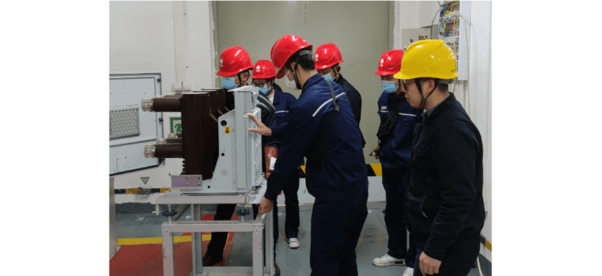
At 12:45 on August 4, 2022, a dispatching center received a report from a 100 MW photovoltaic power generation base. It was reported that the incoming line switchgear on the 35 kV low - voltage side of the main transformer at the collection station was on fire, and the protection action tripped. After receiving the notification, relevant personnel went to the site and carried out on - site accident investigation together with the operation technicians. Through on - site inspection, it was found that the contact box of the switchgear, the handcart, and the copper busbar for the incoming line of phase U of the hard busbar of the switchgear were burned out.
1 Accident Cause Analysis
By analyzing the on - site fault phenomena, as well as the voltage and current waveforms of the fault recording, the main cause of the fault is the poor contact of the V - phase contact of the circuit breaker. Due to the poor contact of the V - phase contact, the temperature of this part abnormally rose and caught fire during operation, causing a short - circuit arc between the U and V phases. As a result, the moving contact of the handcart circuit breaker, the static contact in the contact box, the contact box, and the down - lead of the U phase were burned. At the same time, the current transformer was subjected to arc and electric shock to varying degrees. Through on - site inspection and analysis, the root causes of the poor contact of the V phase mainly come from the following two aspects:
The formation of the heating fault of the high - voltage switchgear is not a short - term sudden occurrence, but a gradual accumulation process. Due to the poor working environment and its own abnormalities, the temperature of the contact surface of the high - voltage switchgear first rises. Superimposed by the continuous action of the current heating effect, the temperature of the contact gradually rises. Once the temperature rise trend gets out of control and the contact temperature exceeds the rated heat resistance standards of the internal current transformer and the insulating bushing, it will damage the equipment, cause a single - phase or two - phase short circuit, amplify the fault damage, and spread to the surrounding auxiliary facilities. In this case, if the protection device did not operate correctly, the spread of the fire and the continuous rise of the temperature would most likely cause an explosion.
2 Exposed Problems
(1) Loopholes in Personnel Operation and Maintenance Management
The personnel of the photovoltaic power generation base have insufficient knowledge of the equipment, are not familiar with the functions of the automation system, do not conduct in - depth research and judgment on the background messages, and the patrol inspection is a mere formality. It was not until the smoke alarm in the high - voltage room went off that they noticed the fire danger. It reflects that the personnel lack systematic training, have insufficient professional knowledge reserves, lack safety vigilance, and fail to effectively perform their equipment operation and maintenance supervision responsibilities.

(2) Lack of Equipment Operation and Maintenance Mechanism
The high - voltage switchgear has not implemented regular maintenance and patrol inspection, and the hidden dangers have gradually accumulated during long - term operation. On the one hand, the high - voltage switchgear has high requirements for mechanical stability and closing reliability. If the circuit breaker handcart is not in place, when running with a large current, the handcart and the cabinet are prone to displacement, the contact resistance of the contacts will increase sharply, causing an arc and even an explosion; on the other hand, the long - term operation will aggravate the mechanical wear of the moving and static contacts, highlighting the hidden danger of poor contact. In addition, there are also risks in the equipment installation link. The level of the handcart track of the handcart circuit breaker and the standardization of the installation operation will damage the integrity of the switchgear and lay the groundwork for accidents.
3 Solutions
(1) Improve the Operation and Maintenance Management System
During the construction phase of photovoltaic and new energy power stations, it is necessary to establish a complete patrol inspection system, conduct simulation drills, and strengthen the systematic training of employees. Improve the knowledge and skill levels of personnel, make them familiar with the equipment principles and automation systems, accurately identify abnormalities in background messages, and carry out patrol inspections in a standardized manner.
(2) Standardize the Maintenance and Operation Process
The operation and maintenance unit of the photovoltaic power station should improve the maintenance system, and strictly require the staff to learn and implement the operation procedures. Clarify the standards of the operation process, ensure that key links such as the seating of the handcart circuit breaker and the contact of the contacts are operated in a standardized manner, and ensure the stable operation of the switchgear from the operation and maintenance process.
(3) Deepen the Management of Preventive Tests
Before the high - voltage switchgear is put into operation, preventive tests must be strictly carried out. During the test, the fault cannot be judged only based on the result of a single test. It is necessary to combine the historical data for vertical comparison and comprehensive analysis, accurately identify the potential defects of the equipment, and eliminate hidden dangers in advance to ensure the reliable operation of the equipment.