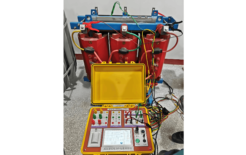
I. DC Resistance Test of Transformer Primary and Secondary Windings:
The DC resistance of transformer primary and secondary windings can be measured using the four-wire (Kelvin) method, which is based on principles related to accurate resistance measurement.
In the four-wire method, two test leads are connected to both ends of the winding under test, while the other two leads are connected to adjacent winding terminals. An AC power source is then applied to the two leads connected to the adjacent windings. Using a multimeter, the DC voltage and current are measured, and the DC resistance of the winding under test is determined. Finally, the DC resistance value is calculated using the four-wire method formula.
It should be noted that the measurement of DC resistance in transformer windings must be performed with the electrical equipment de-energized. Factors such as temperature, humidity, and airborne contaminants must be considered, and care should be taken to prevent interference from test leads contacting other equipment.
II. Insulation Resistance Test of Transformer Windings:
The insulation resistance of transformer windings refers to the resistance between the windings and ground. Two common methods for testing winding insulation resistance are:
Multimeter Measurement Method: Disconnect the transformer’s power supply, connect the two multimeter test leads to the two terminals of the winding, set the multimeter to the resistance (ohmmeter) mode, and read the insulation resistance value. This method is suitable for small-capacity transformers.
Bridge Balance (Wheatstone Bridge) Measurement Method: Connect the transformer to a bridge balance circuit and use the reverse measurement method to determine the winding insulation resistance. The bridge circuit includes an oscillator, detector, and fine-adjustment circuits, which work together to provide a reading of the winding insulation resistance. This method is suitable for large-capacity transformers.
It is important to eliminate external interference before testing and to ensure that the multimeter or bridge measurement device has high accuracy and reliability to guarantee test accuracy. Regularly testing the insulation resistance of transformer windings can effectively prevent electrical failures.
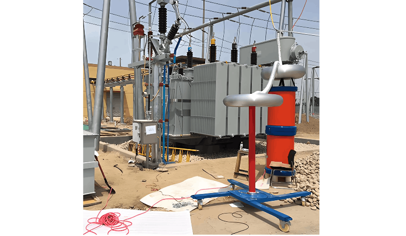
III. AC Withstand Voltage Test of Transformer Windings:
The AC withstand voltage test evaluates the ability of transformer windings to withstand high voltage under an alternating current (AC) electric field at a specified voltage. This test effectively assesses the electrical insulation performance of the transformer and helps prevent electrical failures due to insufficient insulation withstand capability.
The specific steps for this test are as follows:
Prepare test equipment: Including an AC high-voltage generator, current transformer, high-voltage meter, voltmeter, etc.
Ensure safety: Verify that the test equipment is safe and reliable. Personnel must wear protective gear and observe site safety protocols.
Test preparation: Connect the test power supply to the transformer windings. Select the test voltage and frequency according to the transformer’s rated voltage and frequency, and set the test duration.
Test procedure: Apply a stable AC voltage at the selected test current and record the voltage and current values.
Evaluation of results: After the test, judge whether the winding’s withstand voltage capability meets requirements based on established standards and test results.
Note: During the AC withstand voltage test, carefully inspect the power connections, test circuit, insulation resistance, and grounding to ensure the entire test process is safe and reliable. If test results do not meet requirements, the transformer should be repaired or replaced promptly to ensure safe operation of electrical equipment and personnel safety.
IV. Accuracy Test of Transformer Temperature Measurement:
Transformer temperature is a critical reference parameter during normal operation and is vital for ensuring safe operation. To verify the accuracy of temperature measurement, an accuracy test must be performed.
The specific steps for testing transformer temperature measurement accuracy are as follows:
Prepare test equipment: A thermometer and calibration device are required.
Establish measurement standard: Determine the measurement standard for the thermometer based on actual conditions and applicable standards.
Calibration: Place the thermometer in the calibration device and calibrate it. If deviations are found, correct the thermometer based on the actual deviation value.
Conduct temperature measurement: Place the calibrated thermometer at a designated temperature measurement point on the transformer. Record the thermometer reading, along with the test time and ambient temperature.
Analyze results: Compare the measured temperature reading with the actual temperature, calculate the measurement deviation, and evaluate measurement accuracy.
Note: The accuracy test should be conducted at multiple temperature measurement points. Additionally, temperature measurements should be taken when the transformer is operating under stable conditions to obtain the most accurate results. Measurement points with significant deviations should be adjusted or have their temperature probes replaced promptly to ensure accurate readings.