Indoor Metal-Clad Switchgear Equipment

Oliver Watts
08/13/2025

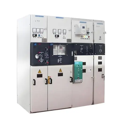
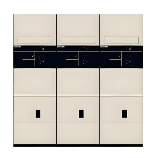
The switchgear comprises a fixed cabinet and removable components (i.e., the draw-out unit or "handcart"). The cabinet enclosure and partition plates of each functional unit are constructed from aluminum-zinc-coated steel sheets, precision-formed using CNC machinery and assembled with bolts. This ensures dimensional consistency, high mechanical strength, and excellent resistance to corrosion and oxidation. The overall protection level of the switchgear enclosure is IP4X; when the circuit breaker compartment door is open, the protection level is IP2X.

The cabinet supports overhead and cable incoming lines, as well as left and right interconnections, offering flexible configuration options for distribution systems to meet diverse design requirements. All installation, commissioning, and maintenance operations can be performed from the front, enabling wall-mounted installation or back-to-back arrangements—optimizing space utilization and reducing overall project costs.

Cabinet Structure

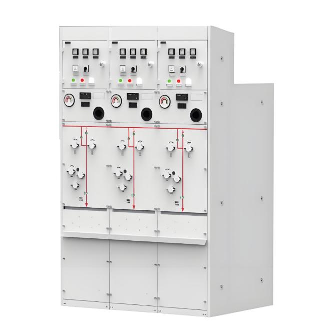
The switchgear cabinet is composed of four independently assembled and interconnected sections: the front cabinet, rear cabinet, instrument chamber, and pressure relief system. These sections are integrated into a cohesive unit. The switchgear is internally compartmentalized into the handcart compartment, busbar compartment, cable compartment, and relay/instrument compartment, each grounded independently with an inter-compartment protection level of IP2X. Except for the relay/instrument compartment, all other compartments are equipped with dedicated pressure relief channels.

The cable compartment is centrally and elevatedly designed, allowing for multiple cable terminations and simplifying on-site installation. Cabinet doors are electrostatically sprayed, providing durability, impact resistance, corrosion resistance, and an aesthetically pleasing finish (with color customizable per user requirements).

A. Handcart Compartment

The handcart compartment is fitted with precision guide rails that allow the circuit breaker handcart to slide and operate smoothly. An automatic shutter mechanism is installed at the front of the static contacts, enhancing operator and maintenance personnel safety by preventing accidental contact with live parts when the handcart is withdrawn.

B. Busbar Compartment

This compartment houses the main busbars. Three openings on the left side wall accommodate busbar insulation sleeves, which electrically isolate adjacent devices and help contain faults, preventing escalation.

C. Cable Compartment

The cable compartment accommodates current transformers, grounding switches, surge arresters, and power cables. A slotted non-metallic or non-magnetic metallic sealing plate can be installed at the bottom, facilitating on-site cable routing and installation.

D. Instrument Chamber

The instrument chamber houses relays, meters, signal indicators, control switches, and other secondary devices. An optional small busbar compartment can be added at the top upon user request, capable of accommodating up to fifteen control busbars.

E. Pressure Relief System

Pressure relief devices are installed above the handcart, busbar, and cable compartments. In the event of an internal arc fault in the circuit breaker, busbar, or cable compartment, the internal pressure rises rapidly. Once a critical pressure threshold is reached, the pressure relief panel at the top automatically opens, safely venting hot gases and pressure outward to protect personnel and surrounding equipment.

Circuit Breaker Handcart

The VD4 vacuum circuit breaker handcart, manufactured by ABB, represents a leading international standard in performance and reliability. The VS1 vacuum circuit breaker handcart, developed and produced by Sanyuan, is the most advanced domestic equivalent. Both types feature a centralized draw-out design, enabling easy operation, visual inspection, handcart insertion/removal, and maintenance. The handcart design ensures interchangeability among units of the same specification. Movement within the switchgear is driven by a screw mechanism, ensuring smooth, reliable, and effortless insertion and withdrawal of the circuit breaker.

Interlocking System for Misoperation Prevention

The switchgear is equipped with a robust and reliable interlocking system that fully complies with the "Five Prevention" requirements, ensuring safe and error-free operation.

Oliver Watts

Hey! I'm Oliver Watts, an electrical engineer in Inspection and Testing. With years of hands - on experience, I ensure electrical systems meet top safety and performance standards. Using advanced gear, I conduct diverse tests, easily spotting issues in both large - scale industrial and small - scale commercial setups. I love teaming up, sharing knowledge, and keeping up with industry regs. Also, I'm skilled at data analysis with software. If you're into electrical inspection or just want to chat engineering, reach out. Let's connect and explore!

What's the maximum efficiency of a power transformer?
The efficiency of a power transformer is influenced by a variety of factors, including its design, size, and operating conditions. In general, power transformers are highly efficient, with typical efficiencies exceeding 95%, and often reaching 98% or higher. However, actual efficiency can vary depending on load levels, voltage ratings, and specific design characteristics.Transformer efficiency (η) is defined as the ratio of output power to input power, expressed as a percentage:η = (Outp
Vziman
08/13/2025
Comparison of Main Protections for Transformer (Differential Protection, Gas Protection)
Transformer Main ProtectionThe main protection for transformers consists of gas protection and differential protection.Gas ProtectionGas protection is a protective mechanism that responds to internal faults within the transformer tank and to a drop in oil level. When an internal fault occurs in the transformer tank, gases generated from the decomposition of transformer oil and insulation materials due to fault currents and arcing flow from the tank toward the upper part of the oil conservator. T
Rockwell
08/12/2025
Configuration and Cases of Backup Protection for Main Transformer
Main Transformer Backup ProtectionThe purpose of main transformer backup protection is to prevent overcurrent in transformer windings caused by external faults, serve as backup protection for adjacent components (busbars or lines), and, where possible, act as backup for the transformer's primary protection in the event of internal faults. Backup protection is used to isolate faults when primary protection or circuit breakers fail.Main transformer zero-sequence protection is a backup protection f
Leon
08/12/2025
Introduction to Transformer Oil Conservator
Introduction to Transformer Oil ConservatorThe oil conservator is a crucial oil storage device for transformers. When the transformer load increases and the oil temperature rises, the insulating oil inside the tank expands due to heat, causing excess oil to flow into the conservator. Conversely, when the temperature decreases, the oil in the conservator flows back into the tank. This process enables automatic oil level regulation, allowing the conservator to serve both oil storage and replenishm
Edwiin
08/12/2025
Inquiry
Download
IEE-Business is dedicated to serving the personnel in the global power industry.
Join IEE-Business, not only can you discover power equipment and power knowledge, but also canhnd like - minded friends!