1. Introduction
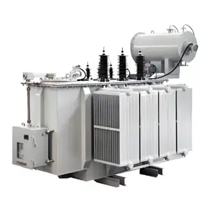
The transformer is an indispensable core component of any electrical power system, and the oil-immersed transformer is the most widely used and longest-established type. It uses insulating oil to provide both electrical insulation and heat dissipation, offering large capacity, stable performance, and relatively low cost. It is extensively deployed in power transmission and distribution, industrial applications, and large power facilities.
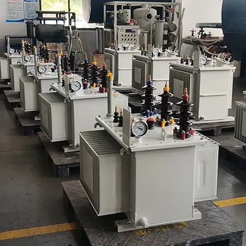
For manufacturers, a clear process flow chart is not only the basis for organizing production and arranging workstations on the shop floor, but also the key document for ensuring consistent product quality, tracing quality issues, and achieving standardized production. This article systematically introduces the complete manufacturing process of an oil-immersed transformer, helping readers understand how a qualified unit is gradually "born" from a pile of raw materials.
2. Basic Structure of an Oil-Immersed Transformer
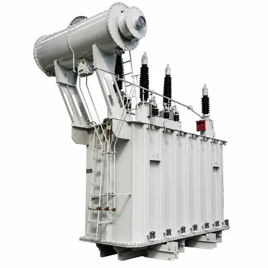
Before discussing the process flow, it is useful to understand the main components of an oil-immersed transformer, because the entire process revolves around the manufacturing and assembly of these parts.
A typical oil-immersed transformer consists mainly of the following parts:
| Component |
Function |
| Core |
The magnetic circuit, laminated or wound from silicon steel sheets |
| Windings (coils) |
The electrical circuit, divided into high-voltage and low-voltage windings |
| Insulation structure |
Turn-to-turn, layer-to-layer, section-to-section and ground insulation |
| Tank and accessories |
Contains the active part and insulating oil, including the tank body, radiators, and conservator (oil reservoir) |
| Tap changer |
Adjusts the voltage level |
| Bushings |
Lead out the HV/LV leads |
| Insulating oil |
Serves dual functions of insulation and heat dissipation |
| Protection and monitoring devices |
Gas relay, thermometers, pressure relief valve, etc. |
The whole process can be summarized along two main lines: one is component manufacturing (core, coil, and other sub-assemblies), and the other is final assembly and testing (active-part assembly, drying, oil filling, testing, and shipping).
3. Overall Process Flow — Overview
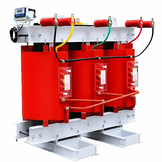
For ease of understanding, the complete manufacturing process of an oil-immersed transformer can be divided into the following major stages:
1.Silicon steel / copper wire / insulation
↓
2. Material supply
↓
3. Raw Material Inspection
↓
4. Core Manufacturing
↓
5. Coil Manufacturing
↓
6. Active-Part Assembly
↓
7. Drying Process
↓
8. Active Part into Tank
↓
9. Oil Filling & Vacuum Treatment
↓
10. Final Assembly (accessories)
↓
11. Type/Routine Testing & Inspection
↓
12. Painting / Packaging / Shipping
From the perspective of "fully oil-immersed, five core steps," the flow chart can be broken down into 11 key operations, described one by one below.

4. Detailed Explanation of the Main Process
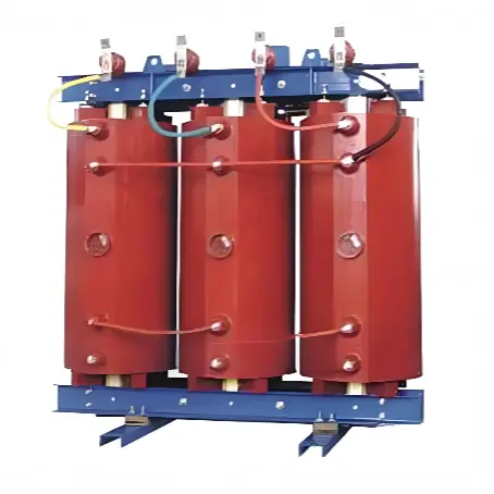
Step 1: Raw Material Inspection and Preparation
Any high-quality transformer starts with strict raw material control.
- Silicon steel sheets: Grain-oriented silicon steel is the foundation of the core magnetic circuit. Its silicon content, grain orientation, magnetic induction, specific iron loss, and thickness tolerance must all be verified. Only qualified sheets can ensure low core loss and low no-load current.
- Magnet wires: Including enamelled round copper wire, paper-wrapped rectangular copper wire, and transposed conductors. Resistance, insulation thickness, dielectric strength, and continuity must be checked to prevent turn-to-turn short circuits during operation.
- Insulation materials: Insulation paper, pressboard, NOMEX paper, laminated wood, and spacer strips must be checked for dielectric strength, mechanical strength, and moisture absorption. Moist or contaminated insulation will directly shorten the transformer's insulation life.
- Insulating oil: Incoming oil must be tested for acid value, moisture content, dielectric dissipation factor, breakdown voltage, and gas content. Only qualified oil is allowed into the production line.
Step 2: Core Manufacturing
The core is the magnetic circuit of the transformer; its quality directly determines no-load losses and noise levels.
- Slitting and cutting: Slit the full coil of silicon steel into strips of the required width along the rolling direction, then shear them into pieces of the required length, punching holes and chamfering edges. Cut edges must be free of burrs, otherwise inter-lamination short circuits will cause heating and excessive losses.
- Stacking: Stack the core laminations one by one according to the design layers and pattern (e.g., staggered joints, four-step, or mitered joints). The number of laminations, compactness, and flatness must be tightly controlled during stacking.
- Clamping and fastening: Press and fix the stacked core using clamp plates (top/bottom clamps) and tie rods to keep the core integral and free of loosening.
- Deburring and inspection: Deburr the core, then perform an initial no-load test to measure core loss; rework if the loss exceeds the limit.
Step 3: Coil (Winding) Manufacturing
The windings are the electrical circuit of the transformer, divided into low-voltage (LV) and high-voltage (HV) windings. The manufacturing process directly determines impedance, losses, and insulation performance.
- Winding: Use winding machines to wind the magnet wire around the insulation cylinder (or directly onto the core limb) according to the designed number of turns and layers. Constant tension must be applied to ensure the coil is tight and dimensionally accurate.
- Insulation wrapping: Simultaneously place layer insulation and turn insulation during winding, and insert spacers or cooling ducts at intervals to ensure oil circulation for heat dissipation.
- Transposition: For transposed conductors, perform transposition at specified intervals during winding to balance the current among parallel conductors and reduce circulating-current losses.
- Pressing and shaping: After winding, dry, shape, and press the coil so its dimensions meet requirements, and trim the end insulation.
- Lead welding: Weld or bolt the HV/LV leads to the coil taps, wrap the connection points with insulation, and fix them on supports.

Step 4: Active-Part Assembly
The active part consists of the core, windings, and the insulation structure.
- Winding onto core: Assemble the already-wound LV and HV coils onto the core limbs (the core may be assembled first and coils threaded on, or the core stacked afterwards, depending on the process), installing insulation cylinders, end insulation rings, and spacers between coil levels.
- Top-yoke lamination (closing the magnetic circuit): After clamping the windings, insert the top-yoke laminations, close and press the magnetic circuit.
- Insulation and fastening: Install all insulation parts (insulating angle rings, electrostatic shields, lead insulation supports, etc.), and press the active part firm using insulation bolts and clamps to prevent loosening during transport and operation.
- Lead connection: Correctly connect the coil leads according to the connection scheme (e.g., Y or Δ), while reserving the tap leads for the tap changer.
Step 5: Drying Process
This is one of the most critical steps affecting transformer life. Insulation materials (paper, pressboard, wood) are strongly polar and readily absorb moisture. If the moisture content is too high, insulation performance drops sharply, potentially causing partial discharge and insulation breakdown.
- Vacuum drying: Place the active part into a large vacuum drying vessel, first applying heat (hot air or steam heating) to drive off moisture, then drawing vacuum to lower the boiling point of water and accelerate moisture evaporation.
- Control targets: After drying, measure the moisture content of the insulation paper, typically required to be reduced to below 0.5%, with insulation resistance reaching the specified value.
- The heating rate must be strictly controlled to avoid sudden temperature rise, which can age and embrittle the insulation material.

Step 6: Active Part into Tank
Lift the dried, cooled active part into a cleaned, inspected tank:
- The inner wall of the tank is coated with anti-corrosion insulating paint, and the active-part base blocks and positioning fixtures are placed at the bottom.
- Lower the active part smoothly into the tank, aligning the coil leads with the bushing openings in the tank cover.
- Install and fasten the tap-changer operating mechanism and lead fasteners, and adjust the active part to the center of the tank.
- Verify the electrical and insulation clearances between the active part and the tank.
Step 7: Vacuum Oil Filling
Oil filling must be combined with vacuum treatment; otherwise air and moisture become trapped in the oil, severely affecting dielectric strength and service life.
- Evacuation: Draw vacuum on the tank to further remove residual moisture and gas trapped in the active part, while preventing air entrapment during filling.
- Vacuum oil filling: Under vacuum, slowly inject filtered, degassed, and dehydrated qualified insulating oil from the bottom of the tank, allowing oil to fill all insulation gaps by gravity.
- Settling and degassing: After filling, maintain vacuum or leave the unit to settle for a period so residual gas can rise and escape.
- Throughout the process, monitor oil moisture, gas content, and particle count online.
Step 8: Final Assembly (Installing Accessories)
After the active part is oil-filled and preliminarily sealed, external accessory installation turns a "bare transformer" into a complete, functional unit:
- Install the conservator (oil reservoir): compensates for oil volume changes with temperature and houses a bladder or diaphragm to isolate oil from air and slow oil aging.
- Install radiators (coolers)/fans: provide heat-dissipation area via natural oil circulation or forced oil circulation.
- Install HV/LV bushings: lead the leads out of the tank while ensuring sufficient creepage distance.
- Install tap changers: both on-load and off-circuit types, mounted on the tank wall with operating mechanisms.
- Install body protection devices: gas (Buchholz) relay, thermometers (oil/winding temperature), pressure relief valve, oil-level gauge, and breather (dehydrating breather).
- Connect external leads and busbars.
Step 9: Factory Testing and Inspection
The fully assembled transformer must pass rigorous testing before shipping. Tests are divided into routine tests and type tests:
Routine tests (performed on every unit)
- Winding insulation resistance and absorption ratio: detects insulation dampness.
- External applied voltage test (winding with bushings): verifies ground insulation strength.
- Induced over-voltage test: verifies turn-to-turn and layer insulation strength.
- No-load test: measures no-load loss and no-load current, verifying core quality.
- Load (short-circuit) test: measures load loss and impedance voltage, verifying winding resistance losses and geometry.
- DC resistance measurement: verifies winding connections and tap-changer contact quality.
- Insulating oil tests: breakdown voltage, dissipation factor, moisture, etc.
Type tests (for new products or important batches)
- Temperature-rise test, lightning impulse test, switching impulse test, short-circuit withstand test, noise test, etc.

Step 10: Painting and Final Inspection
Some transformers require final surface treatment after passing tests:
- De-rust and sand-blast the external tank surface, then apply primer and finish coats (rust-proof and anti-corrosion paint) for improved weather resistance.
- Check the sealing of all flanges, valves, and sealing areas to prevent oil leakage.
- Final cleaning, application of rating plate, nameplate frame, and certificate of conformance.
Step 11: Packaging and Shipping
After final inspection, the transformer is filled with transport-grade oil (or the active part is shipped under nitrogen or vacuum), followed by:
- Moisture-proof, impact-proof, anti-tipping packaging.
- Fixed transport configuration to prevent the active part from shifting during transit.
- Accompanying documentation (test report, instruction manual, certificate, warranty).
5. Quality Control and Common Issues
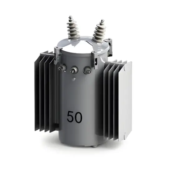
Throughout the process, several quality control points deserve special attention:
- Core loss control: Silicon steel burrs or insufficient stacking compactness raise no-load losses and noise.
- Winding insulation control: Uneven winding tension or incomplete insulation wrapping can concentrate local field intensity.
- Drying/dehydration control: This is fundamental to insulation life; incomplete drying plants the seeds of insulation breakdown.
- Vacuum control during oil filling: Insufficient vacuum leaves high gas content in the oil, accelerating oil deterioration and inducing partial discharge.
- Sealing control: Any oil leakage affects oil level, heat dissipation, and insulation, and must be eliminated before shipping.
Common process defects are often seeded in upstream operations. Large-scale production therefore relies on a three-tier quality control system of first-article inspection + in-process patrol inspection + final full inspection, supported by traceable process cards, ensuring every product can be traced back to raw-material batches and key process parameters.
6. Process Development Trends
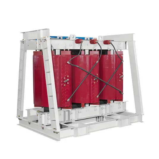
As technology advances, the manufacturing process of oil-immersed transformers continues to evolve:
- Smart manufacturing and automation: Automatic stacking machines, automatic winding machines, AGV logistics, and MES manufacturing execution systems are widely used to improve consistency and traceability.
- Environmentally friendly materials: Promotion of biodegradable insulating oil (e.g., vegetable oil), low-loss high-grade silicon steel (e.g., grain-oriented steel), and higher thermal-class insulation paper.
- Upgraded vacuum drying technology: Moving from simple hot-air drying to drum rotary drying and multi-stage stepped-vacuum drying to further reduce moisture content.
- Digital testing and online monitoring: Combining factory test data with in-service online monitoring to achieve transformer full-lifecycle management.
7. Conclusion
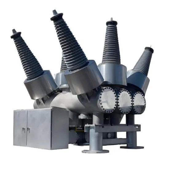
Manufacturing an oil-immersed transformer is a systems engineering effort involving multiple disciplines such as materials science, electromagnetism, heat transfer, and insulation technology. From core laminations and coil winding to active-part drying and vacuum oil filling, and finally to final assembly and testing, every operation is interlinked and mutually constraining. Understanding this process flow chart is not only essential for manufacturers to achieve high quality, high efficiency, and low cost, but is also an important foundation for electrical professionals to understand transformer working principles and maintenance essentials.
I hope this article gives you a systematic and clear understanding of the full path an oil-immersed transformer takes "from raw materials to a qualified product." If you would like more detailed parameters or process requirements for any specific operation, please feel free to explore further.
Contact us:
Edited From:Dyson

 Login