• Product
  • Suppliers
  • Manufacturers
  • Solutions
  • Free tools
  • Knowledges
  • Experts
  • Communities
Search


Handling Substation Blackout: Step-by-Step Guide

Felix Spark
Felix Spark
Field: Failure and maintenance
China

1. Purpose of Handling Total Substation Blackout

A total blackout at a 220 kV or higher substation may lead to widespread power outages, significant economic losses, and instability in the power grid, potentially causing system separation. This procedure aims to prevent voltage loss in main grid substations rated 220 kV and above.

2. General Principles for Handling Total Substation Blackout

  • Establish contact with dispatch as soon as possible.

  • Restore station service power promptly.

  • Quickly restore the DC system.

  • Activate emergency lighting during nighttime.

  • Conduct a comprehensive inspection of all equipment.

  • Isolate faulty equipment.

  • Restore power step-by-step according to dispatch instructions.

  • Prepare and submit an on-site accident report.

3. Main Causes of Total Substation Blackout

  • Single-source substations: fault on the incoming line, tripping on the remote (source) side, or internal equipment failure causing power interruption.

  • Faults on high-voltage busbars or feeder lines leading to upstream tripping of all incoming lines.

  • System-wide faults causing complete voltage loss.

  • Cascading failures or external damage (e.g., natural disasters, sabotage).

4. Handling Total Blackout in Single-Source Substations

In single-source substations, blackouts are typically caused by incoming line faults or tripping on the source side. The timing of power restoration is often uncertain. The response procedure is as follows:

At night, activate emergency lighting first. Conduct a full check of protection actions, alarm signals, meter readings, and circuit breaker status to accurately identify the fault. Disconnect capacitor banks and any feeder breakers with protection activation. Contact dispatch as soon as possible and adjust DC bus voltage. Inspect high-voltage busbars, connected equipment, and main transformers for abnormalities. Check for voltage on the incoming and standby lines. Disconnect non-critical loads.

If no internal fault is found and no protection signals are triggered, the blackout likely resulted from an external line or system fault. In this case, open the de-energized incoming line breaker (to prevent back-feeding into the faulty line), then quickly energize the standby power source. If capacity allows, restore full load; otherwise, prioritize critical loads and station service power. Once the original source is restored, return to normal operation.
Note: When using medium- or low-voltage standby sources, prevent back-feeding to the high-voltage busbar.

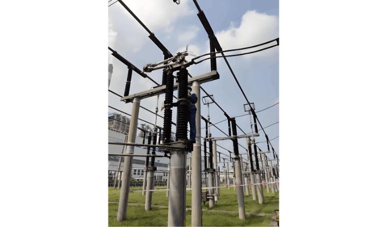
Substation Blackout.jpg

5. Handling Total Blackout in Multi-Source Substations

Multi-source substations (with two or more high-voltage power supplies and sectionalized busbars) rarely experience total blackouts unless operating on a single source. Incoming lines are typically on separate bus sections. When a bus fault occurs, the system can be segmented regardless of whether the fault is isolated.

Procedure:
Activate emergency lighting at night. Review protection and automatic device actions, alarm signals, meter indications, and breaker status to determine the fault based on the operating mode. Disconnect capacitor banks, breakers with protection signals, tie-line breakers, and any breakers with abnormal protection devices. Retain only one incoming power source per bus section; disconnect others. Disconnect non-critical load breakers. Contact dispatch and follow their instructions. Adjust DC bus voltage to normal. Inspect internal equipment (especially high-voltage busbars, connections, and main transformers) for abnormalities. Check incoming lines, standby sources, and tie-lines for voltage verify synchronization, synchronizing devices, and line voltage..

If no internal fault is found, the blackout was likely due to a system fault. Open breakers with protection signals. Open bus section or bus tie breakers to split the system into isolated sections, each with a separate transformer. Retain one station transformer or PT per section to monitor power restoration. Restore power using the first available source. If capacity allows, gradually restore other sections. Before other sources return, open the incoming breakers of de-energized sources to prevent out-of-phase paralleling. Once other sources are available, restore synchronization. After all sources are restored, return to normal configuration and resume power to critical users.

6. General Procedure for Handling Total Substation Blackout

  • Record breaker trip status, protection/automation actions, alarm signals, event logs, and accident characteristics.

  • Perform external inspection of suspected fault equipment and report findings to dispatch.

  • Analyze accident features to determine fault and outage scope.

  • Take action to limit fault escalation and protect personnel/equipment.

  • Restore power to non-fault areas first.

  • Isolate or eliminate the fault and restore power.

  • Implement safety measures for damaged equipment, report to superiors, and arrange professional repairs.

Summary: Record promptly, inspect quickly, report concisely, analyze carefully, judge accurately, limit fault spread, eliminate fault, restore power.

7. What Should On-Duty Personnel Report During a Total Blackout?

When a total blackout occurs, operating personnel must immediately and accurately report the incident to the on-duty dispatcher. The report should include:

  • Time and phenomena of the incident

  • Circuit breaker trip status

  • Relay protection and automatic device actions

  • Changes in frequency, voltage, power flow

  • Equipment status

8. Accident Handling Flowchart

  • After a total blackout, operators should record:

    • Incident time

    • Equipment name

    • Switch position changes

    • Recloser operation

    • Key protection signals

  • Report the above information and load conditions to dispatch and relevant departments for accurate analysis.

  • Check the operational status of affected equipment.

  • Record all signals on protection and automation panels, print fault recorder and microprocessor protection reports. Conduct on-site inspection of all equipment: check actual breaker positions, look for short circuits, grounding, flashovers, broken insulators, explosions, oil spraying, etc.

  • Inspect other related equipment for abnormalities.

  • Report detailed inspection results to dispatch.

  • Execute blackout recovery per dispatch order.

After handling, operators must:

  • Fill in the operation log and breaker operation records

  • Summarize the entire incident process based on breaker trips, protection actions, fault records, and handling steps

Give a tip and encourage the author!
Recommended
Handling 35kV Substation Fault Tripping
Analysis and Handling of Fault Tripping in 35kV Substation Operation1. Analysis of Tripping Faults1.1 Line-Related Tripping FaultsIn power systems, the coverage area is extensive. To meet power supply demands, numerous transmission lines must be installed—posing significant management challenges. Especially for special-purpose lines, installations are often located in remote areas such as suburbs to minimize impact on residential life. However, these remote areas have complex environments, makin
Leon
10/31/2025
 Analysis of Substation Busbar Discharge Faults and Their Solutions
Analysis of Substation Busbar Discharge Faults and Their Solutions
1. Methods for Detecting Busbar Discharge1.1 Insulation Resistance TestThe insulation resistance test is a simple and commonly used method in electrical insulation testing. It is highly sensitive to through-type insulation defects, overall moisture absorption, and surface contamination—conditions that typically result in significantly reduced resistance values. However, it is less effective in detecting localized aging or partial discharge faults.Depending on the equipment’s insulation class and
Edwiin
10/31/2025
How to Handle Common Faults in RMU and Transformer Substations?
1. Ring Main Unit (RMU) and Transformer SubstationThe ring main unit (RMU) and transformer substation is a critical terminal in a distribution ring network system. The operational status of this terminal is directly affected by the performance of the distribution ring network system. Therefore, this section discusses the advantages, system composition, and key characteristics of the distribution ring network.1.1 Advantages of RMU and Transformer SubstationDue to technological limitations, radial
Felix Spark
10/28/2025
What are the common issues in SF₆ gas circuit faults and circuit breaker failure-to-operate faults?
This article categorizes faults into two main types: SF₆ gas circuit faults and circuit breaker failure-to-operate faults. Each is described below:1.SF₆ Gas Circuit Faults1.1 Fault Type: Low gas pressure, but density relay does not trigger alarm or lockout signalCause: Faulty density gauge (i.e., contact not closing)Inspection & Handling: Calibrate actual pressure using a standard gauge. If confirmed, replace the density gauge.1.2 Density Relay Triggers Alarm or Lockout Signal (but pressure
Felix Spark
10/24/2025
Related Products
Send inquiry
Download
Get the IEE Business Application
Use the IEE-Business app to find equipment, obtain solutions, connect with experts, and participate in industry collaboration anytime, anywhere—fully supporting the development of your power projects and business.