• Product
  • Suppliers
  • Manufacturers
  • Solutions
  • Free tools
  • Knowledges
  • Experts
  • Communities
Search


Routine Tests of Circuit Breakers

Encyclopedia
Field: Encyclopedia
0
China


Definition of Routine Tests


Routine tests are regular evaluations conducted to ensure the quality and performance of circuit breakers.


Power Frequency Over Voltage Test


This test checks if circuit breakers can handle unexpected high voltage conditions.


Dielectric Test


Power system can experience temporary overvoltage conditions due to various reasons, like sudden load changes or incorrect tap changer operations. The power frequency over voltage withstand test checks if a circuit breaker’s insulation can handle these overvoltages. Circuit breakers must also endure overvoltages from lightning and switching impulses. While ensuring safety, designers must also consider the cost-effectiveness of the circuit breaker.


To confirm a circuit breaker can handle overvoltage conditions economically, it must pass various dielectric tests. However, only the power frequency over voltage withstand test is considered a routine test for circuit breakers.


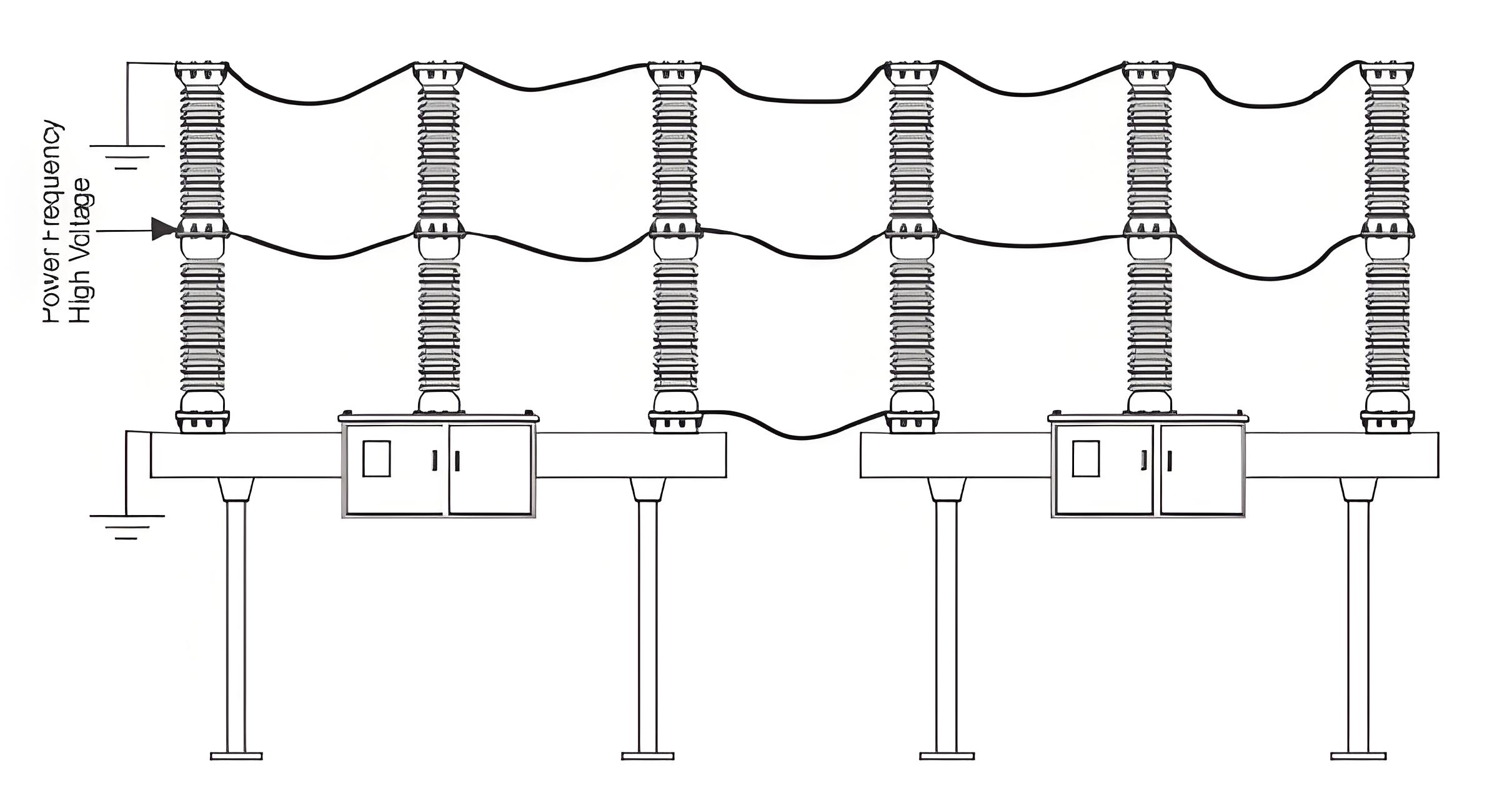
One Minute Dry Power Frequency Voltage Withstand Test


It is assumed that over voltage conditions, at power frequency cannot be sustained beyond one minute time moreover it is actually sustained for much less time than one minute duration. This test is carried out to verify whether the insulation provided in the main circuit of breaker is capable of withstanding power frequency over voltages for long one minute duration or not.


7d8a52f320372286a65b4e7678e33631.jpeg


The test is performed in dry conditions of the breaker. The power frequency voltages, applied to the breaker during the test, are specified in the standard as per the nominal voltage level of the system.


An example of the One Minute Dry Power Frequency Voltage Withstand Test is for an SF6 Circuit Breaker. Typically, the tops of all poles of circuit breakers with the same voltage rating are connected with a copper conductor and earthed. The bases are also properly earthed, and the bottom of all poles are connected with a copper conductor.


This connection then is connected to the phase terminal of single phase high voltage cascaded transformer. High voltage transformer used here is a cascaded auto transformer where input voltage can be varied from zero to several hundred volts and corresponding secondary voltage would be zero to several hundred kilo volts.


During test the voltage is applied at the button terminal of breakers by high voltage cascaded transformer, and varied from 0 to specified value slowly and gently then stay there for 60 second and then slowly decreased to zero. During test the leakage current to the ground to be measured and the leakage current should not cross the specified maximum allowed limit. Any failure of insulation during test indicates the insufficiency of insulation used in breaker.


Dielectric test on auxiliary and control circuit


There may be abnormal over voltage condition in the auxiliary and control supply circuits, too. Hence, the auxiliary and control circuits of breakers should also be gone through short duration power frequency voltage withstand test. Here test voltage of 2000 V is applied for duration of one minute. The insulation of auxiliary and control circuit should pass this test, and there should not be any destructive discharge during the test.


Measurement of the resistance of main circuit


The resistance of main circuit is measured from DC voltage drop across the circuit. In this test, direct current is injected to the circuit and corresponding voltage drop is measured and from this resistance of the circuit is measured. The injected current would be from 100 A to maximum rated current of the circuit breaker. The maximum measured value can be 1.2 times the value obtained at the temperature rise test.


Tightness Test


9ac9c3e27d1c3c7cc2f25fdc16fa96be.jpeg

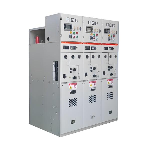
This test is carried out on mainly gas insulated switch-gear. In this test, leakage rate is measured. This test ensures the desired lifespan of the switchgear. Here all the jointing points in the gas containing paths are covered air tightly with thin sheets of polythene (preferably transparent) for more than 8 hours and then the gas density inside this covers is measured by inserting gas detecting port of a gas detector through a hole now created on the covers. The measurement is taken in ppm unit and should be within the specified limit. Maximum limit of gas leakage 3 ppm / 8 hours, is taken as standard.


Visual Checks


The circuit breaker should be visually checked for language and data on the templates, proper identification mark of any auxiliary equipment, color and quality of paint and corrosion on metallic surface, etc.


Mechanical Operation


Circuit breakers are tested for smooth operation at various voltage levels, including rapid auto-reclosing capabilities.


Testing of Circuit Breakers


Comprehensive testing of circuit breakers includes visual inspections, resistance measurement, and ensuring airtightness to maintain performance and safety.


Give a tip and encourage the author!
Recommended
What are the principles of forced re-energization of transmission lines?
Principles of Forced Re-energization of Transmission LinesRegulations for Forced Re-energization of Transmission Lines Correctly select the forced re-energization end of the line. If necessary, change the connection configuration before forced re-energization, taking into account the reduction of short-circuit capacity and its impact on grid stability. There must be a transformer with its neutral point directly grounded on the busbar at the forced re-energization end. Pay attention to the impact
Edwiin
09/04/2025
Analysis of Accident Handling in Transmission Lines
Analysis of Transmission Line Fault HandlingAs a fundamental component of the power grid, transmission lines are widely distributed and numerous, often exposed to diverse geographical and climatic conditions, making them highly susceptible to faults. Common causes include overvoltage, pollution flashover, insulation damage, tree encroachment, and external damage. Line tripping is one of the most frequent faults in power plant and substation operations, with fault types including single-phase-to-
Leon
09/04/2025
The difference between transmission and distribution lines
Transmission lines and distribution lines are both used to carry electrical power from one location to another. However, they differ significantly in key aspects such as primary function, voltage levels, phase configuration, and conductor placement. These differences are essential for understanding their distinct roles in the power system.The Difference Between Transmission and Distribution Line is given below in the tabulated form.Electricity generation is a critical component of the power syst
Edwiin
09/04/2025
Ensuring Reliability: A Deep Dive into Transformer Maintenance
IntroductionElectric transformers are the backbone of modern power distribution systems, silently enabling the reliable delivery of electricity to homes, businesses, and industries. As these critical assets age and the demand for uninterrupted power grows, the importance of diligent transformer maintenance has never been greater. This essay explores the essential role of transformer maintenance, highlighting the value of proactive care, the impact of advanced diagnostic technologies, and the tra
Vziman
09/03/2025
Related Products
  • Cold shrinkable outdoor terminal kit
  • SS2 Operating Mechainsm For Composite Apparatus
  • Stationary contact
  • 550kV 740kV Gas Insulated Switchgear HV (GIS)
Seed Inquiry
Download
Get the IEE Business Application
Use the IEE-Business app to find equipment, obtain solutions, connect with experts, and participate in industry collaboration anytime, anywhere—fully supporting the development of your power projects and business.