What tests need to be conducted on current transformers?

By Oliver, 8 Years in the Electrical Industry
Hi everyone, I'm Oliver, and I've been working in the electrical industry for 8 years.
From early days doing substation equipment commissioning to now managing protection and metering configurations for entire distribution systems, one of the most frequently used devices in my work has been the Current Transformer (CT).
Recently, a friend who's just starting out asked me:
“How do you test current transformers? Is there a simple and effective way to tell if they’re working properly?”
Great question! Many people think testing CTs requires complex equipment and strict procedures, but the truth is — many common issues can be identified with basic skills and tools.
Today, I’ll share with you in plain language — based on my experience over the past few years — how to:
Test current transformers, recognize common faults, and what to look out for during maintenance or inspection.
No jargon, no endless standards — just practical knowledge you can use every day.
1. What Exactly Is a Current Transformer?
Before diving into testing, let’s quickly recap its role.
A current transformer acts like a translator in the power system — it converts large primary currents into smaller secondary currents that can be safely used by protective relays, measuring instruments, and metering devices.
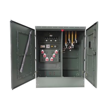
It’s typically installed in switchgear, transformer outgoing lines, or on transmission lines. It forms the foundation of both protection and measurement.
So, if the CT fails, your protection may not work, and your metering will be inaccurate.
2. Seven Common Faults in Current Transformers
Based on my 8 years of field experience and troubleshooting, these are the most common problems you'll encounter with CTs:
2.1 Open Secondary Circuit — The Most Dangerous Issue!
This is one of the most common and dangerous CT failures.
Under normal operation, the secondary side must be closed. If it becomes open, dangerously high voltages can develop — sometimes thousands of volts — which can endanger personnel and damage equipment.
Typical symptoms:
Sparking or arcing sounds;
Meters show no reading or erratic values;
Protection misoperation or failure to operate;
CT overheating or even smoking.
Why does this happen?
Loose terminals;
Broken or disconnected wiring;
Relay coil failure;
Forgetting to short-circuit during maintenance.
My advice:
Always short the secondary before any live inspection;
Use dedicated test terminals;
Regularly check terminal block tightness.
2.2 Incorrect Polarity — The Hidden Killer
Wrong polarity can lead to:
Wrong direction of power flow;
False differential protection alarms;
Reverse meter readings;
Confused protection logic.
How does this happen?
Wiring error during installation;
Failure to recheck after replacement;
Primary conductor installed in the wrong direction.
How to check:
DC method: Battery + multimeter momentary connection;
Or use a polarity tester;
In operation, check via power flow direction.
2.3 Ratio Mismatch — Affects Metering Accuracy
If the actual ratio doesn't match the nameplate, it causes metering errors.
Example: A CT rated at 100/5 shows only 4.7A output — meaning the real ratio is higher than labeled, leading to under-metered energy readings.
Causes:
Manufacturing tolerance;
Core saturation;
Wrong number of primary turns;
High secondary load causing accuracy drop.
Testing methods:
Use a CT ratio tester;
Or apply primary current and measure secondary;
Compare with nameplate data.
2.4 Poor Excitation Characteristics — Impacts Protection Reliability
Especially for protection-grade CTs, poor excitation performance can cause delayed or failed protection.
What is excitation characteristic? Simply put, it’s the magnetization curve of the core under different voltages — showing its linear range and saturation point.
How to test:
Use an excitation characteristic tester;
Check if knee-point voltage meets protection setting requirements;
5P10, 5P20, etc., should meet certain minimum knee-point voltages.
2.5 Aging or Moisture Damage — Especially in Harsh Environments
In humid, dusty, or hot environments, CTs can suffer from insulation degradation or internal moisture.
Symptoms:
Reduced insulation resistance;
Increased partial discharge;
Heating or strange smell;
Fails dielectric withstand test.
Solutions:
Regular insulation resistance testing;
Drying treatment or replace seals;
Consider space heaters in tropical areas;
Ensure proper cabinet sealing.
2.6 Mechanical Damage or Deformation — Caused by External Forces
Sometimes physical damage to the CT body or primary conductor deformation affects performance.
Common causes:
Improper installation;
Handling impact;
Vibration from switching operations;
Corrosion causing structural distortion.
Testing methods:
Visual inspection of housing;
Check for bent primary conductors;
Measure core hole diameter for fit;
Repair or replace if necessary.
2.7 Wiring Errors or Disordered Connections
In multi-winding CTs, incorrect wiring can lead to:
Mixed use of windings for protection, measurement, and metering;
Signal interference between circuits;
Abnormal monitoring data.
My advice:
Clearly define winding functions (protection, measurement, metering);
Label connections clearly;
Double-check wiring after installation or replacement;
Use a tester to verify each winding output.
3. Common Tools and Steps for On-Site Testing
Common Testing Tools:
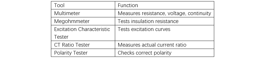
On-Site Testing Procedure (Summary):
Visual inspection for damage or burn marks;
Measure insulation resistance (primary to ground, secondary to ground, primary to secondary);
Check polarity correctness;
Test current ratio against nameplate;
Test excitation characteristics (especially for protection windings);
Verify wiring correctness and tightness;
Monitor operation under load (if possible).
4. My Final Recommendations
As someone with 8 years of hands-on experience in this field, I want to remind all professionals:
“The CT may be small, but its role is huge. Don’t wait until a trip happens to realize it had a problem.”
Especially in critical circuits like main transformer differential, feeder protection, and metering points, regular testing and careful maintenance are essential.
Here are my recommendations for different roles:
For Maintenance Personnel:
Learn to read CT nameplate information;
Master basic testing techniques (insulation testing, polarity check);
Recognize common fault symptoms;
Report abnormalities promptly.
For Technical Staff:
Understand CT selection and calculation;
Know protection winding characteristics;
Interpret system short-circuit parameters;
Analyze excitation curves.
For Managers or Procurement Teams:
Define clear technical specifications;
Choose reliable manufacturers;
Request full test reports from suppliers;
Maintain equipment records for traceability.
5. Closing Thoughts
Though small, current transformers are the eyes and ears of the entire power system.
They’re not just about reducing current — they form the basis of protection, the foundation of metering, and the guarantee of safety.
After 8 years in the electrical field, I often say:
“Details determine success or failure, and proper testing ensures safety.”
If you ever run into difficulties testing CTs, dealing with frequent protection misoperations, or unsure if your parameters are suitable, feel free to reach out — I’m happy to share more hands-on experience and solutions.
May every current transformer operate stably and accurately, safeguarding the reliability of our power grid!
— Oliver