The grounding disconnect switch of a pad-mounted transformer is a switching device used to isolate the pad-mounted transformer from the grounding cable. It is an essential component of pad-mounted transformer equipment and plays a critical role in protecting the safety of the transformer equipment. The grounding disconnect switch of a pad-mounted transformer serves important functions in grounding down leads, grounding switching, auxiliary grounding, and lightning protection.
Its functions include:
Protecting personnel safety: During maintenance and inspection of the pad-mounted transformer, opening the grounding disconnect switch ensures complete electrical isolation between the transformer and external circuits, preventing safety hazards caused by accidental operation.
Preventing reverse current flow: Equipment grounding and grounding cables are installed to prevent internal currents from endangering personnel. However, during short-circuit or ground-fault conditions in the pad-mounted transformer, reverse current flow may occur. The grounding disconnect switch can disconnect the grounding cable from the equipment, thereby preventing reverse current and safeguarding both equipment and personnel.
Ensuring stable equipment operation: Proper use of the grounding disconnect switch effectively reduces voltage fluctuations and prevents excessively high or low voltages or currents, thus maintaining operational stability of the equipment.
Preventing foreign object intrusion: When the pad-mounted transformer is out of service, the grounding disconnect switch helps prevent foreign objects or animals from entering the enclosure, protecting the equipment from external damage.
It should be noted that when operating the grounding disconnect switch, relevant operating procedures and safety standards must be strictly followed to ensure operations are performed under safe conditions. Additionally, during inspection or replacement of the grounding disconnect switch, the normal operation of the pad-mounted transformer must be maintained, and care must be taken to avoid any adverse impact on the equipment during the process.

Below is an introduction to the specific wiring method of the grounding disconnect switch for pad-mounted transformers:
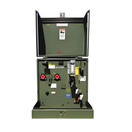
The wiring of the grounding disconnect switch shall comply with equipment requirements. It should be arranged in a “box” shape at the top of the transformer enclosure cabinet, with the connection point positioned higher than the highest metal support bracket.
Grounding conductor brackets shall be installed on both the upper and lower sides of the grounding disconnect switch. Multiple mounting holes shall be provided on the central rod of each bracket to allow flexible and secure installation according to actual needs, ensuring stability and reliability.
When the grounding switch is required, insert the grounding conductor into the socket of the grounding disconnect switch and maintain firm contact to achieve an effective grounding connection.
The basic principle of the grounding disconnect switch is to disconnect one end of the grounding conductor—connected between the upper and lower terminals of the equipment—from the earth, thereby enabling the function of connecting or disconnecting the grounding path. Therefore, during installation, the manufacturer’s wiring diagram and operation manual must be strictly followed, and installation and wiring should be carried out according to the actual dimensions of the equipment.
In summary, during the installation and wiring of the grounding disconnect switch, operating procedures must be carefully observed, and the equipment wiring diagram must be thoroughly reviewed and strictly followed to ensure both equipment and personnel safety. If the operator lacks relevant experience or capability, please contact the manufacturer or qualified professionals for installation, operation, or maintenance.