In China's power system, the 6 kV, 10 kV, and 35 kV grids generally adopt a neutral-point ungrounded operation mode. The distribution voltage side of the main transformer in the grid is usually connected in delta configuration, which provides no neutral point for connecting a grounding resistor.
When a single-phase ground fault occurs in a neutral-point ungrounded system, the line-to-line voltage triangle remains symmetrical, causing minimal impact on user operations. Moreover, when the capacitive current is relatively small (less than 10 A), some transient ground faults can self-extinguish, which is highly effective in improving power supply reliability and reducing power outage incidents.
However, with the continuous expansion and development of the power industry, this simple method no longer meets current demands. In modern urban power grids, the increasing use of cable circuits has led to significantly larger capacitive currents (exceeding 10 A). Under such conditions, the ground arc cannot be reliably extinguished, resulting in the following consequences:
Intermittent extinction and reignition of the single-phase ground arc generates arc-ground overvoltages with amplitudes reaching up to 4U (where U is the peak phase voltage) or even higher, lasting for extended durations. This poses severe threats to the insulation of electrical equipment, potentially causing breakdowns at weak insulation points and leading to major losses.
Sustained arcing causes air ionization, degrading the insulation of surrounding air and making phase-to-phase short circuits more likely.
Ferroresonance overvoltages may occur, easily damaging potential transformers (PTs) and surge arresters, and in severe cases, even causing arrester explosions. These consequences seriously endanger the insulation of grid equipment and threaten the safe operation of the power system.
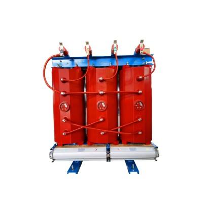
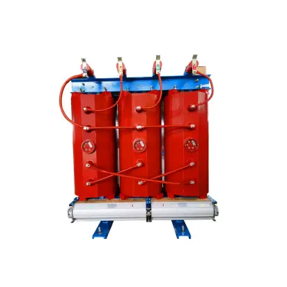
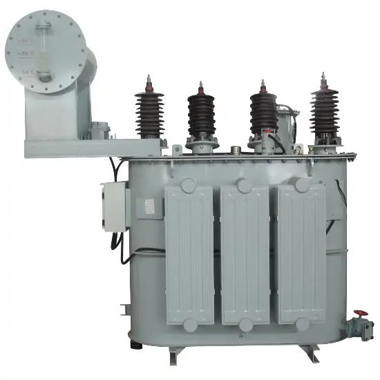
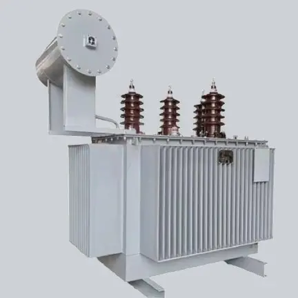
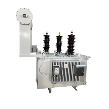
To prevent the above accidents and provide sufficient zero-sequence current and voltage for reliable operation of ground fault protection, an artificial neutral point must be created so that a grounding resistor can be connected. To address this need, grounding transformers (commonly referred to as "grounding units") were developed. A grounding transformer artificially creates a neutral point with a grounding resistor, typically with a very low resistance value (usually less than 5 ohms).
Additionally, due to its electromagnetic characteristics, the grounding transformer presents high impedance to positive- and negative-sequence currents, allowing only a small excitation current to flow through its windings. On each core limb, two winding sections are wound in opposite directions. When equal zero-sequence currents flow through these windings on the same core limb, they present low impedance, resulting in minimal voltage drop across the windings under zero-sequence conditions.
During a ground fault, positive-, negative-, and zero-sequence currents flow through the windings. The winding exhibits high impedance to positive- and negative-sequence currents, but for zero-sequence current, the two windings on the same phase are connected in series with opposite polarity. Their induced electromotive forces are equal in magnitude but opposite in direction, effectively canceling each other out, thus presenting low impedance.
In many applications, grounding transformers are used solely to provide a neutral point with a small grounding resistor and do not supply any load; therefore, many grounding transformers are designed without a secondary winding. During normal grid operation, the grounding transformer operates essentially in a no-load condition. However, during a fault, it carries fault current only for a short duration.

In a neutral-point low-resistance grounded system, when a single-phase ground fault occurs, highly sensitive zero-sequence protection quickly identifies and temporarily isolates the faulty feeder. The grounding transformer is active only during the brief interval between the occurrence of the ground fault and the operation of the zero-sequence protection to clear the fault. During this time, zero-sequence current flows through the neutral grounding resistor and the grounding transformer,given by

where U is the system phase voltage, R1 is the neutral grounding resistor, and R2 is the additional resistance in the ground fault loop.
Based on the above analysis, the operational characteristics of grounding transformers are: long-term no-load operation with short-term overload capability.
In summary, a grounding transformer artificially creates a neutral point to connect a grounding resistor. During a ground fault, it presents high impedance to positive- and negative-sequence currents but low impedance to zero-sequence current, enabling reliable operation of ground fault protection.
Currently, grounding transformers installed in substations serve two purposes:
Supplying low-voltage AC power for substation auxiliary use;
Creating an artificial neutral point on the 10 kV side, which—when combined with an arc suppression coil—compensates for capacitive ground fault current during 10 kV single-phase ground faults, thereby extinguishing the arc at the fault point. The principle is as follows:
Along the entire length of transmission lines in a three-phase power grid, capacitances exist between phases and between each phase and ground. When the grid neutral is not solidly grounded, the phase-to-ground capacitance of the faulted phase becomes zero during a single-phase ground fault, while the phase-to-ground voltages of the other two phases rise to √3 times the normal phase voltage. Although this increased voltage does not exceed the insulation strength designed for safety, it increases their phase-to-ground capacitance.
The capacitive ground fault current during a single-phase fault is approximately three times the normal per-phase capacitive current. When this current is large, it easily causes intermittent arcing, leading to overvoltages in the LC resonant circuit formed by grid inductance and capacitance, with magnitudes reaching 2.5 to 3 times the phase voltage. The higher the grid voltage, the greater the risk from such overvoltages. Therefore, only systems below 60 kV may operate with an ungrounded neutral, as their single-phase capacitive ground fault currents are relatively small. For higher voltage levels, a grounding transformer must be used to connect the neutral point through impedance to ground.
When the 10 kV side of a substation main transformer is connected in delta or wye without a neutral point, and the single-phase capacitive ground fault current is large, a grounding transformer is required to create an artificial neutral point, enabling connection to an arc suppression coil. This forms an artificial neutral grounding system—the primary function of the grounding transformer. During normal operation, the grounding transformer withstands balanced grid voltage and carries only a small excitation current (no-load condition).
The neutral-to-ground potential difference is zero (ignoring minor neutral displacement voltage from the arc suppression coil), and no current flows through the arc suppression coil. Assuming a phase-C-to-ground short circuit occurs, the zero-sequence voltage resulting from three-phase asymmetry flows through the arc suppression coil to ground. Like the arc suppression coil itself, the induced inductive current compensates for the capacitive ground fault current, eliminating the arc at the fault point.
In recent years, multiple misoperations of grounding transformer protection have occurred in 110 kV substations in a certain region, severely affecting grid stability. To identify the root causes, analyses were conducted on the reasons for these misoperations, and corresponding measures were implemented to prevent recurrence and provide reference for other regions.
Currently, 10 kV feeders in 110 kV substations increasingly use cable outgoing lines, significantly increasing the single-phase capacitive ground fault current in the 10 kV system. To suppress overvoltage magnitudes during single-phase ground faults, 110 kV substations have begun installing grounding transformers to implement a low-resistance grounding scheme, establishing a zero-sequence current path. This allows selective zero-sequence protection to isolate ground faults based on fault location, preventing arc reignition and overvoltage, thus ensuring safe power supply to grid equipment.
Starting in 2008, a certain regional grid retrofitted its 110 kV substation 10 kV systems to low-resistance grounding by installing grounding transformers and associated protection devices. This enabled rapid isolation of any 10 kV feeder ground fault, minimizing grid impact. However, recently, five 110 kV substations in the region experienced repeated misoperations of grounding transformer protection, causing substation outages and severely disrupting grid stability. Therefore, identifying causes and implementing corrective measures is essential to maintain regional grid security.
1.Analysis of Causes for Grounding Transformer Protection Misoperation
When a 10 kV feeder experiences a ground short-circuit fault, the zero-sequence protection on the faulty feeder at the 110 kV substation should operate first to isolate the fault. If it fails to do so correctly, the grounding transformer’s zero-sequence protection will act as backup, tripping the bus tie breaker and both sides of the main transformer to isolate the fault. Thus, correct operation of 10 kV feeder protection and breakers is critical to grid safety. Statistical analysis of misoperations in five 110 kV substations shows that the primary cause is the failure of 10 kV feeders to correctly clear ground faults.
Principle of 10 kV Feeder Zero-Sequence Protection:
Zero-sequence CT sampling → Feeder protection activation → Circuit breaker tripping.
From this principle, the zero-sequence CT, feeder protection relay, and circuit breaker are key components for correct operation. The following analyzes misoperation causes from these aspects:
1.1 Zero-sequence CT error causing grounding transformer protection misoperation.
During a 10 kV feeder ground fault, the faulty feeder’s zero-sequence CT detects fault current, triggering its protection to isolate the fault. Simultaneously, the grounding transformer’s zero-sequence CT also senses the fault current and initiates protection. To ensure selectivity, the 10 kV feeder zero-sequence protection is set with lower current and shorter time settings than the grounding transformer protection. Current settings: grounding transformer—75 A primary, 1.5 s to trip 10 kV bus tie, 1.8 s to block 10 kV auto-transfer, 2.0 s to trip transformer low-voltage side, 2.5 s to trip both sides; 10 kV feeder—60 A primary, 1.0 s to trip breaker.
However, CT errors are inevitable. If the grounding transformer CT has a -10% error and the feeder CT has a +10% error, the actual operating currents become 67.5 A and 66 A—nearly equal. Relying solely on time grading, a 10 kV feeder ground fault could easily cause the grounding transformer’s zero-sequence overcurrent protection to trip prematurely.
1.2 Incorrect cable shield grounding causing misoperation.
110 kV substation 10 kV feeders use shielded cables with shields grounded at both ends—a common EMI mitigation practice. Zero-sequence CTs are toroidal types installed around cables at switchgear outgoing terminals. During ground faults, unbalanced currents induce signals in the CT to activate protection. However, with both-end shield grounding, induced currents in the shield also pass through the zero-sequence CT, creating false signals. Without proper mitigation, this impairs feeder zero-sequence protection accuracy, leading to grounding transformer backup tripping.
1.3 10 kV feeder protection failure causing misoperation.
Modern microprocessor-based relays offer improved performance, but varying manufacturer quality and poor heat dissipation remain issues. Fault statistics show that power supply modules, sampling boards, CPU boards, and trip output modules in 10 kV feeder protections are most prone to failure. Undetected faults can cause protection refusal, triggering grounding transformer misoperation.
1.4 10 kV feeder breaker failure causing misoperation.
With aging, frequent operations, or inherent quality issues, 10 kV switchgear failures—especially in control circuits—are increasing. In less-developed mountainous areas, older GG-1A switchgear remains in service with higher ground fault rates. Even if zero-sequence protection operates correctly, breaker failure (e.g., burnt trip coil preventing operation) leads to grounding transformer misoperation.
1.5 High-impedance ground faults on two 10 kV feeders (or severe single high-impedance fault) causing misoperation.
When two feeders experience same-phase high-impedance ground faults, individual zero-sequence currents may stay below the 60 A trip threshold (e.g., 40 A and 50 A), so feeder protections only alarm. But the summed current (90 A) exceeds the grounding transformer’s 75 A setting, causing premature tripping. With all-cable 10 kV feeders, normal capacitive currents can reach 12–15 A. Even a single severe high-impedance fault (e.g., 58 A) plus normal capacitive current approaches 75 A. System oscillations could then easily trigger grounding transformer misoperation.
2.Measures to Prevent Grounding Transformer Protection Misoperation
Based on the above analysis, the following measures are recommended:
2.1 To prevent CT error-induced misoperation
Use high-quality zero-sequence CTs; rigorously test CT characteristics before installation and reject any with >5% error; set protection pickup values based on primary current; verify settings by primary injection testing.
2.2 To prevent incorrect cable shield grounding
Cable shield grounding conductors must pass downward through the zero-sequence CT and be insulated from cable trays. No grounding contact should occur before passing through the CT. Expose metal ends for primary injection testing; insulate the rest reliably.
If the shield grounding point is below the CT, the conductor must not pass through the CT. Avoid routing the shield grounding conductor through the middle of the CT.
Enhance technical training so relay protection and cable teams fully understand CT and shield grounding installation methods.
Strengthen acceptance procedures with joint inspections by relay, operations, and cable teams.
2.3 To prevent feeder protection failure
Select proven, reliable protection devices; replace aging or frequently faulty units; enhance maintenance; install air conditioning and ventilation to prevent high-temperature operation.
2.4 To prevent feeder breaker failure
Use reliable, mature switchgear; phase out old GG-1A cabinets in favor of sealed, spring- or motor-charged types; maintain control circuits; use high-quality trip coils.
2.5 To prevent high-impedance fault misoperation
Immediately patrol and repair feeders upon zero-sequence alarm; reduce feeder lengths; balance phase loads to minimize normal capacitive currents.
3. Conclusion
As more regional grids install grounding transformers and associated protection to improve structure and stability, recurring misoperation incidents highlight the need to address adverse effects. This paper analyzes primary causes of grounding transformer protection misoperation and proposes countermeasures, providing guidance for regions that have installed or plan to install such systems.