Parallel Resonance

Parallel resonance occurs in an alternating current (AC) circuit when the circuit current aligns in phase with the applied voltage. This phenomenon specifically takes place in circuits that feature an inductor and a capacitor connected in parallel.
To gain a more comprehensive understanding of parallel resonance, let's examine the circuit diagram presented below.

Let's consider an inductor with an inductance of L henries and an internal resistance of R ohms, which is connected in parallel with a capacitor having a capacitance of C farads. An alternating supply voltage of V volts is applied across these parallel - connected elements.
In this parallel - resonant circuit configuration, the circuit current Ir will be in perfect phase alignment with the supply voltage only when the condition expressed by the following equation is met.

Phasor Diagram
The phasor diagram of the given circuit is shown below:

Let's consider an inductor with an inductance of L henries, which has an inherent resistance of R ohms, connected in parallel with a capacitor of capacitance C farads. An alternating supply voltage of V volts is applied across this parallel combination of the inductor and capacitor.
In this electrical setup, the circuit current Ir will precisely align in phase with the supply voltage if and only if the specific condition described by the following equation is satisfied.


If R is very small as compared to L, then resonant frequency will be

Effect of Parallel Resonance
At parallel resonance line current Ir = IL cosϕ or

Therefore, the circuit impedance will be given as:

Based on the preceding discussion of parallel resonance, the following key conclusions can be drawn:
Impedance Characteristics
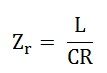
During parallel resonance, the circuit impedance manifests as purely resistive. This is because the frequency - dependent terms that typically govern the behavior of inductors and capacitors in an AC circuit cancel each other out, leaving only a resistive component. When the inductance (L) is measured in henries, the capacitance (C) in farads, and the resistance (R) in ohms, the circuit impedance Zr is also expressed in ohms.
High Impedance Value
The magnitude of Zr is notably high. At the point of parallel resonance, the ratio L/C reaches a significant value, which directly contributes to the elevated impedance of the circuit. This high impedance is a distinctive feature that sets parallel - resonant circuits apart from others.
Low Circuit Current
Given the formula for circuit current Ir = V/Zr, and considering the high value of Zr, the resulting circuit current Ir is very small. Even with a relatively constant supply voltage V, the high impedance acts as a strong barrier to current flow, keeping the current drawn from the source to a minimum.
Branch Current vs. Line Current
The currents flowing through the capacitor and the inductor (coil) are substantially larger than the line current. This occurs because the impedance of each individual branch (the inductor - resistance combination and the capacitor) is much lower than the overall circuit impedance Zr. As a result, a greater amount of current is able to circulate within these branches compared to the current that flows through the main line of the circuit.
Rejector Circuit Nature
Due to its ability to draw minimal current and power from the electrical mains, the parallel - resonant circuit is often referred to as a "rejector circuit." It effectively .


