
Ang parallel resonance mahitabo ha usa ka alternating current (AC) circuit kon ang circuit current mag-align sa phase ha applied voltage. Ang phenomenon ini nagkakatugyan hain nga mga circuit nga mayda inductor ug capacitor nga giconnect ha parallel.
Para makakuha hin mas komprehensibo nga pagkamando han parallel resonance, itonon kita an circuit diagram nga ginpresentar ha ibaba.

Itonon kita an inductor nga mayda inductance nga L henries ug internal resistance nga R ohms, nga giconnect ha parallel uban an capacitor nga mayda capacitance nga C farads. An alternating supply voltage nga V volts ig-apply ha parallel-connected elements ini.
Ha parallel-resonant circuit configuration ini, an circuit current Ir mag-align ha perfect phase alignment ha supply voltage tikang lang kon sasabot an kondisyon nga ipahayag ha sumusunod nga equation.

Phasor Diagram
An phasor diagram han given circuit mahitabo ha ibaba:

Itonon kita an inductor nga mayda inductance nga L henries, nga mayda inherent resistance nga R ohms, nga giconnect ha parallel uban an capacitor nga mayda capacitance nga C farads. An alternating supply voltage nga V volts ig-apply ha parallel combination han inductor ug capacitor ini.
Ha electrical setup ini, an circuit current Ir mag-align ha phase ha supply voltage tikang lang kon sasabot an specific condition nga ipahayag ha sumusunod nga equation.


Kon R kaunti kumpara ha L, an resonant frequency will be

Ha parallel resonance line current Ir = IL cosϕ or

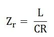
Therefore, the circuit impedance will be given as:

Based on the preceding discussion of parallel resonance, the following key conclusions can be drawn:
Ha parallel resonance, an circuit impedance manifests as purely resistive. This is because the frequency-dependent terms that typically govern the behavior of inductors and capacitors in an AC circuit cancel each other out, leaving only a resistive component. When the inductance (L) is measured in henries, the capacitance (C) in farads, and the resistance (R) in ohms, the circuit impedance Zr is also expressed in ohms.
The magnitude of Zr is notably high. At the point of parallel resonance, the ratio L/C reaches a significant value, which directly contributes to the elevated impedance of the circuit. This high impedance is a distinctive feature that sets parallel-resonant circuits apart from others.
Given the formula for circuit current Ir = V/Zr, and considering the high value of Zr, the resulting circuit current Ir is very small. Even with a relatively constant supply voltage V, the high impedance acts as a strong barrier to current flow, keeping the current drawn from the source to a minimum.
The currents flowing through the capacitor and the inductor (coil) are substantially larger than the line current. This occurs because the impedance of each individual branch (the inductor-resistance combination and the capacitor) is much lower than the overall circuit impedance Zr. As a result, a greater amount of current is able to circulate within these branches compared to the current that flows through the main line of the circuit.
Due to its ability to draw minimal current and power from the electrical mains, the parallel-resonant circuit is often referred to as a "rejector circuit." It effectively .


