• Product
  • Suppliers
  • Manufacturers
  • Solutions
  • Free tools
  • Knowledges
  • Experts
  • Communities
Search


Shunt Resistor: What is it And How Does it Work?

Electrical4u
Field: Basic Electrical
0
China

What is a Shunt Resistor?

A shunt resistor (or shunt) is defined as a device that creates a low resistance path to force most of the electric current through the circuit to flow through this path. In most cases, a shunt resistor is made up of a material having a low-temperature coefficient of resistance, giving it a very low resistance over a wide temperature range.

Shunt resistors are commonly used in current measuring devices called “ammeters”. In an ammeter, the shunt resistance is connected in parallel. An ammeter is connected in series with a device or circuit.

How Does a Shunt Resistor Work?

A shunt resistor has a low resistance. It provides a low resistance path to current, and it is connected in parallel with a current measuring device.

The shunt resistor uses ohm’s law to measure the current. The resistance of the shunt resistor is known. And it is connected in parallel with the ammeter. So, the voltage is the same.

Hence, if we measure the voltage across a shunt resistance, we can measure the current passing through the device by the equation below of ohm’s law.

  \[ I = \frac{V}{R} \]

Using a Shunt Resistor to Measure Current

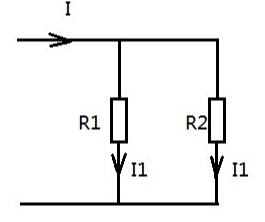
Consider an ammeter that has resistance Ra and measures a very small current Ia. For exceeding the range of an ammeter, a shunt resistor Rs is placed parallel with Rm.

The circuit diagram of these connections is shown in the figure below.


image.png


The total current supplied by the source is I. It is divided into two paths.

According to Kirchhoff’s current law (KCL), 

 \[ I = I_s + I_a \]

Where,

Is = current passes through resistance Rs (shunt current)

Ia = current passes through resistance Ra

\[ I_s = I - I_a \]

The shunt resister Rs is connected parallel with resistor Ra. Hence the voltage drop across both resisters are equal.

  \[ V_s = V_a \]

\[ I_s R_s = I_a R_a \]

  \[ (I - I_a) R_s = I_a R_a \]

  \[ IR_s - I_a R_s = I_a R_a \]

  \[ IR_s = I_a R_a + I_a R_s \]

  \[ IR_s = I_a (R_a + R_s) \]

  \[ \frac{I}{I_a} = \frac{ R_a + R_s }{R_s} \]

  \[ N = 1 + \frac{R_a}{R_s} \]

Where N is a multiplying power of shunt.

How to Build a Shunt Resistor

The shunt resister can be built with very thin copper wires. The length and size of the shunt resister depend on the resistance you require.

The resistance of the shunt resistor will decide the range of the ammeter.

If you use 10 AWG (2.59 mm diameter) copper wire, the resistance of this wire is 0.9989 ohms per 1000 feet. This resistance may vary according to the quality of a wire.

Hence, make sure of the resistance before using it. To calculate the required length of wire for a particular value of shunt resistor, use the below equation.

  \[ Length \, of \, wire = \frac{Required \, shunt \, resistance \, (m \Omega)}{Resistance \, per \, 1000 \, feet }  \]

For example, if you require a shunt of 0.5 mΩ and use 10 AWG wire, put the above values in this equation.

  \[ Length \, of \, wire = \frac{0.5}{0.9989} \]

\[ Length \, of \, wire \approx 0.5 feet \]

What Is the Purpose of Shunt Resistor (Applications)?

The application of shunt resister is as listed below.

  • A shunt resistor is used in an electrical circuit to protect against overvoltage.

  • It is used in a current measuring device.

  • It is used to bypass defective devices. (When a number of components are connected in series, one component is failed to operate, it will break the entire circuit. In this condition, the shunt resistor bypasses the fail component and continues the circuit path.)

  • A shunt resistor with a capacitor is used in a circuit to avoid the problem of high-frequency noise.

  • It is used in overload protection control circuits, including power supplies.

How to Size a Shunt Resistor

Generally, a shunt resistor is used in the current measuring device. The size of the shunt resister will decide the range of the ammeter.

The size of the shunt resister depends on the maximum current rating. It is calculated by the voltage drop at the maximum current rating.

Let say a shunt resistor is designed for maximum current 100 A and voltage drop 50 mV. Typically, the voltage drop at maximum current is 50 mV, 75 mV, or 100 mV.

In this example, we can calculate the resistance of shunt resister by ohm’s law.


\[ V = I R \]

  \[ 50 \times 10^{-3} = 100 R \]

  \[ R = 0.5 m \Omega \]

Source: Electrical4u.

Statement: Respect the original, good articles worth sharing, if there is infringement please contact delete.

Give a tip and encourage the author!
Recommended
Difference Between Electromagnet and Permanent Magnet
Electromagnets vs. Permanent Magnets: Understanding the Key DifferencesElectromagnets and permanent magnets are the two primary types of materials that exhibit magnetic properties. While both generate magnetic fields, they differ fundamentally in how these fields are produced.An electromagnet generates a magnetic field only when an electric current flows through it. In contrast, a permanent magnet inherently produces its own persistent magnetic field once it has been magnetized, without requirin
Edwiin
08/26/2025
Working Voltage in Power System
Working VoltageThe term "working voltage" refers to the maximum voltage that a device can withstand without sustaining damage or burning out, while ensuring the reliability, safety, and proper operation of both the device and associated circuits.For long-distance power transmission, the use of high voltage is advantageous. In AC systems, maintaining a load power factor as close to unity as possible is also economically necessary. Practically, heavy currents are more challenging to handle than hi
Encyclopedia
07/26/2025
What is a Pure Resistive AC Circuit?
Pure Resistive AC CircuitA circuit containing only a pure resistanceR(in ohms) in an AC system is defined as a Pure Resistive AC Circuit, devoid of inductance and capacitance. Alternating current and voltage in such a circuit oscillate bidirectionally, generating a sine wave (sinusoidal waveform). In this configuration, power is dissipated by the resistor, with voltage and current in perfect phase—both reaching their peak values simultaneously. As a passive component, the resistor neither
Edwiin
06/02/2025
What is a Pure Capacitor Circuit?
Pure Capacitor CircuitA circuit comprising only a pure capacitor with capacitanceC(measured in farads) is termed a Pure Capacitor Circuit. Capacitors store electrical energy within an electric field, a characteristic known ascapacitance(alternatively referred to as a "condenser"). Structurally, a capacitor consists of two conductive plates separated by a dielectric medium—common dielectric materials include glass, paper, mica, and oxide layers. In an ideal AC capacitor circuit, the current
Edwiin
06/02/2025
Seed Inquiry
Download
Get the IEE Business Application
Use the IEE-Business app to find equipment, obtain solutions, connect with experts, and participate in industry collaboration anytime, anywhere—fully supporting the development of your power projects and business.