• Product
  • Suppliers
  • Manufacturers
  • Solutions
  • Free tools
  • Knowledges
  • Experts
  • Communities
Search


Ultra-Fast Current Limiter (FCL): Isang Revolutionary na Solusyon na May Millisecond-Level na Interruption ug Economic Benefits

  1. Overview: Redefining Speed and Economics in Short-Circuit Protection

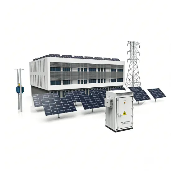
Ania nga solusyon nagfokus sa usa ka ultra-fast short-circuit current limiting device, gihimo aron matubag ang kasagaran nga problema sa pagdako sa short-circuit currents ug matiyak ang kalambigitan sa power grids ug equipment.

1.1 Core Features

  • Ultra-Fast Interruption Speed: Nag-detekta og sayop ug nagsugyot sa current sa loob sa 1 milisegundo, efektibo nga natigom ang short-circuit current bago maabot ang iyang peak.
  • High Interruption Capacity:
    • Suitable para sa 12kV/17.5kV systems: Maximum breaking capacity nga 210kA (RMS).
    • Applicable para sa 24kV/36kV/40.5kV systems: Maximum breaking capacity nga 140kA (RMS).

1.2 Core Advantages

  • Economic Efficiency: Nagoperate sa parallel uban sa current-limiting reactors aron mapasabot ang pinaka cost-effective nga limiting solution. Naausab ang pagpuli sa entire switchgear panels o transformers tungod sa pagdako sa short-circuit currents, makapahinayog sa investment sa bag-ong o upgraded substations.
  • Broad Compatibility: Ideal para sa interconnecting switchgear ug substations; sa daghang mga scenario (e.g., parallel operation of multiple transformers), kini ang tuman-ang teknikal nga solusyon.
  • Exceptional Reliability:
    • Hinatagan og higit pa sa 60 ka tuig nga global operational experience (gin-invent niadtong 1955), ginpatunay sa liboan ka proyekto sa buhatan sa mundo.
    • Ang estadistika gikan sa halos 4,000 ka yunit nagpakita og average operation frequency nga raka una sa pipila ka tuig, nagpakita sa stable ug reliable nga performance.
  1. Key Technical Q&A

No.

Key Question

Core Answer

1

Unsa ang peak short-circuit current?

Ang maximum instantaneous value human sa unang cycle human sa short-circuit fault, resulta sa superposition sa periodic ug non-periodic components. Igihiusa kini og dako nga electromagnetic forces (testing dynamic stability) ug heat (testing thermal stability).

2

Bakit limitahan ang peak short-circuit current?

Ang peak currents nga mas taas sa rated withstand parameters sa equipment mahimong moguba sa switchgear, circuit breakers, current transformers, ug cable connectors pinaagi sa dako nga electromagnetic forces.

3

Pamuno kung unsaon pag-adapt sa parallel operation of multiple transformers?

Para sa switchgear nga may withstand capability nga 2Ik, sa usa ka system nga adunay apat ka transformers (4Ik) sa parallel, makaya ang perfect adaptation pinaagi sa pag-install og fast current limiters sa gitas nga bus sections (e.g., sa pagitan sa sections 1-2 ug 3-4).

4

Unsa ang tripping criteria? Unsaon pag-iwas sa false trips?

Ang control unit nag-monitor sa instantaneous current (I) ug rate of current rise (di/dt). Ang trip mag-trigger lang kung parehas sila mag-exceed sa set thresholds. Kini nga dual criterion siguro nga ang tikang nga short-circuit currents lang ang gi-interrupt, ang general faults gibahin sa downstream circuit breakers.

5

Unsaon ang maintenance human sa operation?

Ang core operating component (conductive bridge) may modular design ug mahimong ibalik sa repair. Ang kinahanglan ra i-replace mao ang internal conductive core, inductive filler, ug parallel fuses; ang uban pang mga komponent reusable, makapahinayog sa kaayo ka gamay nga maintenance costs.

  1. Core Functions and Value

3.1 Core Function

Nag-detekta ug nagsugyot sa sayop sa initial rising stage of short-circuit current (within 1ms), efektibo nga natigom ang damage sa power equipment tungod sa insufficient dynamic ug thermal stability. Perfectly nag-compensate sa inherent limitations sa traditional circuit breakers—"slow to act and unable to suppress the first half-wave peak current."

3.2 Comparative Advantages

Comparison Object

Advantage Details

Traditional Circuit Breakers

Ang breakers mag-operate sa tens of milliseconds aron interrupt, dili makaputli sa impact sa unang peak current. Kini nga limiter nag-responde sa 1ms, nagsugyot sa actual peak short-circuit current sa mas gamay nga level.

Current-Limiting Reactors

Nag-iwas sa voltage drop, active losses (copper losses), ug reactive losses associated sa reactors sa continuous operation. Ug nag-iwas usab sa generator regulation issues resulta sa integration sa reactor.

3.3 Applicable Scenarios

  • Power plants
  • Large industrial grid substations
  • Specific key circuits/scenarios: Transformer/generator feeder circuits, bus tie sections, reactor bypass applications, ug interconnection points between grids ug captive power sources.
  1. Structure and Design

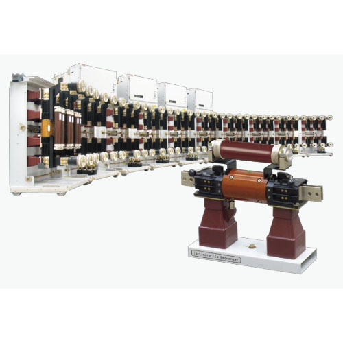
4.1 Overall Composition

Ang three-phase AC system fast current limiter gisangpot sa:

  • 3 conductive bridge bases
  • 3 conductive bridges
  • 3 matching current transformers
  • 1 control unit

4.2 Key Component Details

Component Name

Composition / Features

Key Parameters / Rules

Conductive Bridge Base

Includes mounting plate, insulators, pulse transformer, ug connectors with quick couplings

- Rated current ≥2500A ug voltage 12/17.5kV: Bolted connections.
- Pulse transformer: ≤17.5kV (installed only at the bottom); ≥24kV (installed at both top ug bottom for reliable isolation).

Conductive Bridge

Conductive core ug inductive filler encapsulated in an insulating cover

Upon tripping, ang inductive filler mag-trigger, driving the conductive core to break rapidly at its pre-cut; current then transfers to the parallel fuse.

Matching Current Transformer

Bushing or block type, series-connected in the main circuit

Features a gapped core (high overcurrent factor, low remanence) ug shielded primary/secondary windings (low impedance) to ensure measurement accuracy ug speed.

Control Unit

Includes power supply, control, indication, ug anti-interference units

- Dimensions: 600mm (W) × 1450mm (H) × 300mm (D); weight: 100kg.
- Indication unit: 5 flag relays (3-phase trip indication + readiness monitoring + power supply monitoring).

  1. Working Principle: Achieving 1ms Current Limiting

5.1 Core Composition

Ang device essentially an intelligent parallel combination of two components:

  • "Extremely fast switch (conductive bridge)": Carries rated current during normal operation ug opens instantaneously during faults.
  • "High-breaking-capacity fuse": Ultimately interrupts the high current after the switch opens.

5.2 Operation Sequence

  1. Detection: Matching current transformers (CTs) continuously collect current signals; ang control unit calculates instantaneous current (I) ug rate of current rise (di/dt).
  2. Judgment: When both I ug di/dt exceed set values, ang control unit immediately issues a trip command (independent three-phase judgment ug triggering).
  3. Interruption: The trip capacitor discharges into the pulse transformer, triggering the inductive filler in the conductive bridge. This generates high-pressure gas, causing the conductive core to rupture at its pre-cut within 1ms.
  4. Current Limiting: Arc resistance increases rapidly, transferring current to the parallel fuse. The fuse begins limiting within 0.5ms ug extinguishes the arc completely at the next current zero, clearing the fault.

5.3 Auxiliary Units

  • Power Unit: Provides 150V DC power to charge the trip capacitor ug supply electronic components. Includes a watchdog circuit to monitor system health.
  • Anti-Interference Unit: All external wiring passes through this unit, providing effective protection against external electromagnetic interference ug preventing false operations.
  1. Commissioning and Testing

6.1 Testing Requirements

Regular functional testing is required, which can be executed by users or ABB service engineers.

6.2 Dedicated Equipment

  • Simulator: Temporarily replaces the conductive bridge during testing. Its built-in neon lamp lights up upon receiving a trip pulse, indicating proper operation.
  • Test Plug & Test Instrument: Used to check trip output voltage ug overall functionality. Features a user-friendly interface ug easy operation (dimensions: 400×215×320mm; weight: 11kg).
  1. Scope of Supply and Parameters

7.1 Supply Models

Model Type

Applicable Scenarios

Core Configuration

Discrete Components

For installation in existing switchgear

3 bases + 3 conductive bridges + 3 CTs + 1 control unit

Drawout Cabinet

For metal-clad switchgear

Conductive bridges mounted on withdrawable carts (with isolating switch function); CTs fixed; control unit installed in the low-voltage compartment

Fixed Cabinet

- For 12/17.5/24kV systems
- Mandatory for 36/40.5kV systems

All components fixed inside the cabinet. For 36/40.5kV systems, the control unit is often installed in a separate control box.

7.2 Key Technical Parameters (Example: Discrete Components)

Note: ¹ indicates forced air cooling is required; compatible with 50/60Hz frequency.


Technical Parameter

Unit

12kV

17.5kV

24kV

36/40.5kV

Rated Voltage

V

12000

17500

24000

36000/40500

Rated Current

A

1250-5000¹

1250-4000¹

2500-4000¹

1250-3000¹

Rated Short-Circuit Breaking Current (Max.)

kA RMS

210

210

210

140

  1. Typical Application Scenarios

Application Scenario

Core Issue

Solution Value

Parallel System Operation

Short-circuit current from multiple transformers in parallel exceeds switchgear ratings

1. Allows reduced system impedance, minimizing voltage drop.
2. Optimizes transformer load distribution, reducing losses.
3. Enables uninterrupted load transfer during faults, improving supply reliability.

Grid-Captive Power Interconnection

Captive generator operation causes excessive short-circuit current at the common coupling point

The only rational solution. Can be equipped with directional tripping (requires CT at generator neutral) to ensure operation only for grid-side faults.

Bypassing Current-Limiting Reactors

Reactors in continuous operation cause losses ug voltage drop

Bypasses reactors during normal operation (zero loss, zero voltage drop); rapidly interrupts during short circuits, diverting current to the reactor for limiting.

Selective Application of Multiple Units

Selective operation required when multiple limiters are installed on multi-section buses

Uses "current vector sum" criterion to ensure only the limiter closest to the fault operates. Supports up to 5 transformers in parallel (using 4 limiters).

  1. Service and Support
  • Contact Email: Support@rw-relay.com
08/26/2025
Gipareserbado
Engineering
Integradong Solusyon sa Hybrid Power ng Hangin at Araw para sa mga Malalayong Isla
AbstractKini nga propuesta nagpakita og usa ka bag-ong integradong solusyon sa enerhiya nga nahimong gipagsam niadtong wind power, photovoltaic power generation, pumped hydro storage, ug seawater desalination technologies. Ang layun mao ang sistemikong pagtubag sa core challenges nga gigrap sa mga remote islands, kasinabi na ang difficult grid coverage, high costs sa diesel power generation, limitations sa traditional battery storage, ug scarcity sa freshwater resources. Ang solusyon makakamit a
Engineering
Isa ka Intelligent Wind-Solar Hybrid System nga may Fuzzy-PID Control para sa Enhanced Battery Management ug MPPT
AbstractAng proyekto kini nagpakita og sistema sa pag-generate og kapang-osob nga gipangasiwaan pinaagi sa teknolohiya sa advanced control, ang katuyoan mao ang efektibong ug ekonomikal nga pag-ahon sa panginahanglan sa kapang-osob sa mga remote areas ug espesyal nga application scenarios. Ang core sa sistema naka-center sa usa ka intelligent control system nga gipangasiwaan pinaagi sa ATmega16 microprocessor. Ang sistema kini nagperforma og Maximum Power Point Tracking (MPPT) para sa parehas wi
Engineering
Mura nga Solusyon sa Hikabug-Init sa Hangin: Buck-Boost Converter & Smart Charging Mureduksyon sa Gastos sa Sistema
AbstractKini nga solusyon nagproporsyona og usa ka bag-ong mataas na efektibong sistema sa pag-generate sa hybrid wind-solar power. Ang sistema nagsangpot sa mga pangunahon nga kahibaw-hibaw sa kasinatngan nga teknolohiya sama sa mababa nga paggamit sa energy, maikling lifespan sa battery, ug dili matinud-anon nga estabilidad sa sistema, gamiton ang fully digitally controlled buck-boost DC/DC converters, interleaved parallel technology, ug intelligent three-stage charging algorithm. Kini nagpada
Engineering
Sistema nga Optimisado sa Hybrid Wind-Solar Power: Komprehensibong Solusyon sa Disenyo para sa mga Aplikasyon sa Off-Grid
Introduksyon ug Background​​1.1 mga Hamon sa Single-Source Power Generation Systems​Ang tradisyonal nga standalone photovoltaic (PV) o wind power generation systems adunay inherent nga drawbacks. Ang PV power generation maapektuhan sa diurnal cycles ug kondisyon sa panahon, samtang ang wind power generation gipasabot sa unstable nga wind resources, resulta sa significant nga pagkakaiba sa output sa power. Aron masiguro ang continuous nga suplay sa power, importante ang large-capacity battery ban
Inquiry
Pangutana
Pangutana sa IEE-Business Application
Pangita og mga equipment gamit ang IEE-Business app asa asa ug kailan man sugad og pagkuha og solusyon pagsulay sa mga eksperto ug pagpadayon sa industriya nga pakisayran suportahan ang imong proyekto sa kuryente ug negosyo