• Product
  • Suppliers
  • Manufacturers
  • Solutions
  • Free tools
  • Knowledges
  • Experts
  • Communities
Search


Ultra-Fast Current Limiter (FCL): A Revolutionary Solution Featuring Millisecond-Level Interruption and Economic Benefits Is aistriúchán: Ultra-Fast Current Limiter (FCL): Solútar Innovatiúil le Sreabhadh ag Leibhéal na nMilliseocond agus Buntáistí Airgeadais

  1. Forbhreathnú: Athchóiriú ar Luas agus Ardoilimh i gCosaint Chur isteach Forrach

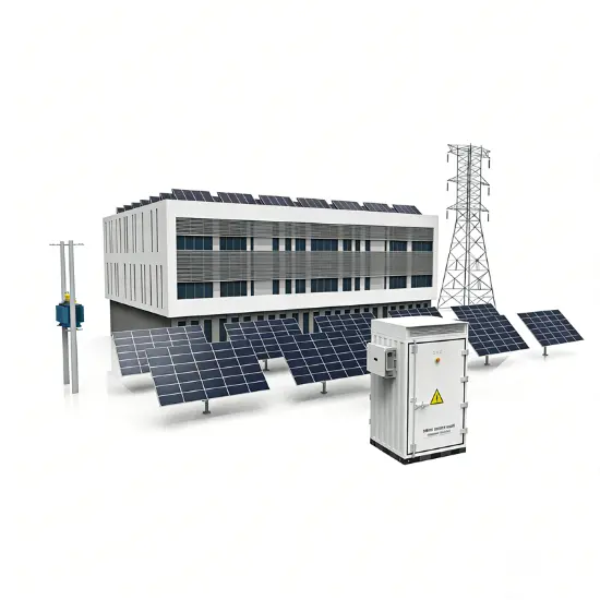
Bhíonn an tionscadal seo dírithe ar dispositiúin cosanta forrach cúrsaíochta an-ghluais, a chruthaíodh chun dul i ngleic leis an dúshlán atá ag fás sna cúrsaíochtaí forrach ollmhóra agus chun síntiús na dtionchar agus na hequipáid a chinntiú.

1.1 Bonn Feidearthachtaí

  • An-ghluaiseacht Cosanta Forrach: Aithneoidh sé deifir agus cosnaigh an cúrsa íosta laistigh de 1 milliseocond, ag coinneáil an cúrsa forrach go hiondúil roimh é a bhualadh a pheac.
  • Ardoilimh Cosanta Forrach:
    • Taobh amuigh do chórais 12kV/17.5kV: Tuarascáil briseadh is airde 210kA (RMS).
    • Taobh amuigh do chórais 24kV/36kV/40.5kV: Tuarascáil briseadh is airde 140kA (RMS).

1.2 Bonn Buntáiste

  • Honairíocht Ghineolaíoch: Oibríonn sé in eitilt le reacaireacha cosanta cúrsaíochta chun an tionscal is saor a sholáthar. Seachnas an riail a dhéanamh ar painéal sluithe go hiomlán nó trandaitheoirí mar gheall ar ardú ar chúrsaí forrach, ag laghdú go suntasach ar infheistíocht i staidchlúicheanna nua nó nuashonraithe.
  • Comhoibritheacht Leathan: Is é an tionscadal is fearr do nascadh sluithe agus staidchlúicheanna; i go leor cásanna (mar shampla, obair comhpháirteach ar mhórán trandaitheoirí), is é an t-aon réiteach teicniúil féideartha.
  • Claontaí Cónspóideach:
    • Níos mó ná 60 bliain taithí oibriú domhanda (cruthaíodh é i 1955), dearbhaíodh é i mílte tionscadal ar fud an domhain.
    • Staicstic ó thart ar 4,000 aonad a léiríonn modh oibre amháin gach ceithre bliana, ag léiriú feidhmíocht staibhle agus iontaofa.
  1. PríomhCeisteanna Teicniúla Q&A

Uimhir

PríomhCheist

Freagra Bonn

1

Cén sórt is ea an cúrsa forrach bhearna?

An luach sochraidh is airde le linn an chéad chothrom anois tar éis do chur isteach forrach tarlú, ag cruthú as an iolráid de phríomhaíochtaí ciúla agus gan phríomhaíocht. Cruthaíonn sé fórsaí eleimeadracha mór (tástáil stabilité dinimici) agus te (tástáil stabilité thearma).

2

Cén fáth cosaint ar an cúrsa forrach bhearna?

D'fhéadfadh cúrsaí bhearna a bhfuil siad os cionn na rátála dheitheanas don tionscal a dhéanamh damáiste ar sluithe, sluithe briseadh, transformaitheoirí cúrsa, agus ceangail cabhlacha trí fórsaí eleimeadracha láidre.

3

Cómo adaptarse a la operación en paralelo de múltiples transformadores?

Para equipos con una capacidad de resistencia de 2Ik, en un sistema con cuatro transformadores (4Ik) en paralelo, se puede lograr una adaptación perfecta instalando limitadores de corriente rápidos entre las secciones del bus (por ejemplo, entre las secciones 1-2 y 3-4).

4

What are the tripping criteria? How to avoid false trips?

The control unit simultaneously monitors instantaneous current (I) and rate of current rise (di/dt). A trip is triggered only when both exceed set thresholds. This dual criterion ensures only hazardous short-circuit currents are interrupted, while general faults are handled by downstream circuit breakers.

5

How to maintain after operation?

The core operating component (conductive bridge) features a modular design and can be returned for repair. Only the internal conductive core, inductive filler, and parallel fuses need replacement; other components are reusable, ensuring very low maintenance costs.

  1. Core Functions and Value

3.1 Core Function

Detects and limits faults during the initial rising stage of short-circuit current (within 1ms), effectively preventing damage to power equipment due to insufficient dynamic and thermal stability. It perfectly compensates for the inherent limitations of traditional circuit breakers—“slow to act and unable to suppress the first half-wave peak current.”

3.2 Comparative Advantages

Comparison Object

Advantage Details

Traditional Circuit Breakers

Breakers take tens of milliseconds to interrupt, unable to avoid the impact of the first peak current. This limiter responds within 1ms, restricting the actual peak short-circuit current to a lower level.

Current-Limiting Reactors

Avoids voltage drop, active losses (copper losses), and reactive losses associated with reactors in continuous operation. Also eliminates the need to address generator regulation issues caused by reactor integration.

3.3 Applicable Scenarios

  • Power plants
  • Large industrial grid substations
  • Specific key circuits/scenarios: Transformer/generator feeder circuits, bus tie sections, reactor bypass applications, and interconnection points between grids and captive power sources.
  1. Structure and Design

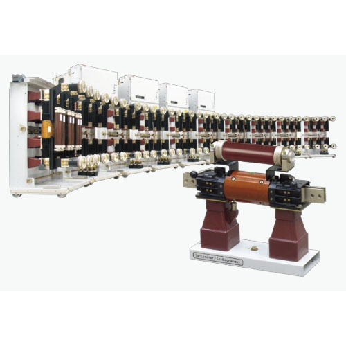
4.1 Overall Composition

The three-phase AC system fast current limiter consists of:

  • 3 conductive bridge bases
  • 3 conductive bridges
  • 3 matching current transformers
  • 1 control unit

4.2 Key Component Details

Component Name

Composition / Features

Key Parameters / Rules

Conductive Bridge Base

Includes mounting plate, insulators, pulse transformer, and connectors with quick couplings

- Rated current ≥2500A and voltage 12/17.5kV: Bolted connections.
- Pulse transformer: ≤17.5kV (installed only at the bottom); ≥24kV (installed at both top and bottom for reliable isolation).

Conductive Bridge

Conductive core and inductive filler encapsulated in an insulating cover

Upon tripping, the inductive filler is triggered, driving the conductive core to break rapidly at its pre-cut; current then transfers to the parallel fuse.

Matching Current Transformer

Bushing or block type, series-connected in the main circuit

Features a gapped core (high overcurrent factor, low remanence) and shielded primary/secondary windings (low impedance) to ensure measurement accuracy and speed.

Control Unit

Includes power supply, control, indication, and anti-interference units

- Dimensions: 600mm (W) × 1450mm (H) × 300mm (D); weight: 100kg.
- Indication unit: 5 flag relays (3-phase trip indication + readiness monitoring + power supply monitoring).

  1. Working Principle: Achieving 1ms Current Limiting

5.1 Core Composition

The device is essentially an intelligent parallel combination of two components:

  • "Extremely fast switch (conductive bridge)": Carries rated current during normal operation and opens instantaneously during faults.
  • "High-breaking-capacity fuse": Ultimately interrupts the high current after the switch opens.

5.2 Operation Sequence

  1. Detection: Matching current transformers (CTs) continuously collect current signals; the control unit calculates instantaneous current (I) and rate of current rise (di/dt).
  2. Judgment: When both I and di/dt exceed set values, the control unit immediately issues a trip command (independent three-phase judgment and triggering).
  3. Interruption: The trip capacitor discharges into the pulse transformer, triggering the inductive filler in the conductive bridge. This generates high-pressure gas, causing the conductive core to rupture at its pre-cut within 1ms.
  4. Current Limiting: Arc resistance increases rapidly, transferring current to the parallel fuse. The fuse begins limiting within 0.5ms and extinguishes the arc completely at the next current zero, clearing the fault.

5.3 Auxiliary Units

  • Power Unit: Provides 150V DC power to charge the trip capacitor and supply electronic components. Includes a watchdog circuit to monitor system health.
  • Anti-Interference Unit: All external wiring passes through this unit, providing effective protection against external electromagnetic interference and preventing false operations.
  1. Commissioning and Testing

6.1 Testing Requirements

Regular functional testing is required, which can be executed by users or ABB service engineers.

6.2 Dedicated Equipment

  • Simulator: Temporarily replaces the conductive bridge during testing. Its built-in neon lamp lights up upon receiving a trip pulse, indicating proper operation.
  • Test Plug & Test Instrument: Used to check trip output voltage and overall functionality. Features a user-friendly interface and easy operation (dimensions: 400×215×320mm; weight: 11kg).
  1. Scope of Supply and Parameters

7.1 Supply Models

Model Type

Applicable Scenarios

Core Configuration

Discrete Components

For installation in existing switchgear

3 bases + 3 conductive bridges + 3 CTs + 1 control unit

Drawout Cabinet

For metal-clad switchgear

Conductive bridges mounted on withdrawable carts (with isolating switch function); CTs fixed; control unit installed in the low-voltage compartment

Fixed Cabinet

- For 12/17.5/24kV systems
- Mandatory for 36/40.5kV systems

All components fixed inside the cabinet. For 36/40.5kV systems, the control unit is often installed in a separate control box.

7.2 Key Technical Parameters (Example: Discrete Components)

Note: ¹ indicates forced air cooling is required; compatible with 50/60Hz frequency.


Technical Parameter

Unit

12kV

17.5kV

24kV

36/40.5kV

Rated Voltage

V

12000

17500

24000

36000/40500

Rated Current

A

1250-5000¹

1250-4000¹

2500-4000¹

1250-3000¹

Rated Short-Circuit Breaking Current (Max.)

kA RMS

210

210

210

140

  1. Typical Application Scenarios

Application Scenario

Core Issue

Solution Value

Parallel System Operation

Short-circuit current from multiple transformers in parallel exceeds switchgear ratings

1. Allows reduced system impedance, minimizing voltage drop.
2. Optimizes transformer load distribution, reducing losses.
3. Enables uninterrupted load transfer during faults, improving supply reliability.

Grid-Captive Power Interconnection

Captive generator operation causes excessive short-circuit current at the common coupling point

The only rational solution. Can be equipped with directional tripping (requires CT at generator neutral) to ensure operation only for grid-side faults.

Bypassing Current-Limiting Reactors

Reactors in continuous operation cause losses and voltage drop

Bypasses reactors during normal operation (zero loss, zero voltage drop); rapidly interrupts during short circuits, diverting current to the reactor for limiting.

Selective Application of Multiple Units

Selective operation required when multiple limiters are installed on multi-section buses

Uses "current vector sum" criterion to ensure only the limiter closest to the fault operates. Supports up to 5 transformers in parallel (using 4 limiters).

  1. Service and Support
  • Contact Email: Support@rw-relay.com
08/26/2025
Moltaigh
Engineering
Seirbhís Chumhacht Intégraide Wind-Solar Do Oileáin Iarmhara
AchoimreTá an tionscadal seo ag tabhairt isteach ar sholúid iontaisigh comhtháite a chumasaíonn go dochasach fuinneamh gaoithe, geasar rinnleabhar, stóráil uisce deargadha, agus teicnící déisiú mara. Tá sé agus é a scéal chun na príomhchuidiúla atá os comhair oileáin iarmhara a réiteach go córasach, lena n-áirítear cúlra gréasáin, costas ard ghineadh deiseil, teorainneacha stórála bataí traidisiúnta, agus scarthaíocht uisce fiontair. Céimníonn an tionscadal coibhneas agus neamhspleáchas in "solá
Engineering
Córas Iontach Meascán Gaoth-Grian le Rialú Fuzzy-PID chun Bainistiú Batára a Fheabhsú agus MPPT
Achoimre​Tá forbairt an tsíste gineadh fhuinnimh ghaoithe-solais seo bunaithe ar theicneolaíocht rialú casta, agus is é an aidhm aige an riachtanas fuinnimh i réimsí thoir agus in úsáid shainiúil a réiteach go hiontaofa agus go geilleagarach. Tá an croílár den tsíste i gcóras rialú intleachtach atá bunaithe ar micripróiseálaí ATmega16. Déanann an córas seo Rianú Pointe Fuinnimh Mhaighnimithe (MPPT) do fhuinneamh ghaoithe agus solais, agus úsáideann algoríom casta atá comhdhíolte de PID agus rial
Engineering
Cost-Effective Wind-Solar Hybrid Solution: Buck-Boost Converter & Smart Charging Reduce System Cost Is é an t-eolas seo ná: An tionscadal Wind-Solar Hybird Inmhíníoch: An Buck-Boost Converter & Íomharghiú Intileach Lúdaíonn Costas na Sísteama
Achoimre​Molann an réiteach seo córas geineireachta feidhmeachta ardchumais a bhfuil méitheolaíocht ghrian-ánmhaighneach. Tá sé ag déileáil le príomhfhadhbanna sa teicneolaíocht reatha—mar shampla, úsáid íseal airgid, meascáin bata scortha, agus stabacht an chórais go dona—le lucht a dhéanamh den chuid seachtrach deontúil DC/DC buck-boost, teicneolaíocht iarmheascáin, agus algoritam luchtaithe tríshocra. Seo a chur ar fáil rianú pointe cumais uasta (MPPT) tríd réimsi gaoise agus greana gréine ní
Engineering
Córas Aon Chuileacháin Gaoithe-Solair: Solútar Forfheidhmeoireachta Comhtháthaithe do Chásanna Ionchais Amach As An Grid
Ínidh agus Cúlra​​1.1 Dúshláin Sistimeacha Giniúnaíochta Aonfhuinniúla​Tá lagmhaireachtaí suntasacha ag sistimeacha giniúnaíochta aonfhuinniúla solair (PV) nó gaoithe traidisiúnta. Tá an tionscal PV súdaithe ag ciorcail laethúla agus coinníde, agus tá an tionscal gaoithe bunaithe ar fhuinniúchán an ghaoithe neamhstábla, rud a chuirpíonn athrú mór ar an tionscal. Chun a bheith cinnte go leanann an tionscal, is gá bancbataí meascáin mhóra chun stóráil agus comhoibriú. Ach, mar gheall ar an úsáid f
Seol fiosrúchán
Íoslódáil
Faigh an tApliú IEE Business
Úsáid an t-aip IEE-Business chun eochair uirlis a aimsiú déantar réiteach a fháil nasc le saineolaithe agus glacadh páirte i gcothromhachtú tionscail ar bith áit ar bith go láidir tacú le forbairt do thionscadal forbartha agus gnó