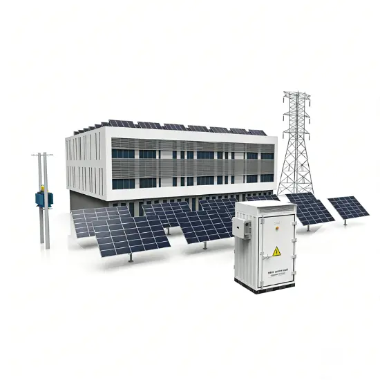
Narito ang solusyon na nakatuon sa ultra-mabilis na short-circuit current limiting device, na disenyo upang lubusang tugunan ang lumalaking hamon ng labis na short-circuit currents at tiyakin ang kaligtasan ng mga power grid at kagamitan.
1.1 Puno ng mga Katangian
1.2 Puno ng mga Advantages
|
No. |
Key Question |
Core Answer |
|
1 |
Ano ang peak short-circuit current? |
Ang maximum instantaneous value sa unang cycle pagkatapos ng pagkakamali ng short-circuit, na resulta ng superposition ng periodic at non-periodic components. Ito ay nag-generate ng malalaking electromagnetic forces (testing dynamic stability) at init (testing thermal stability). |
|
2 |
Bakit limitin ang peak short-circuit current? |
Ang peak currents na lumampas sa equipment-rated withstand parameters ay maaaring masira ang switchgear, circuit breakers, current transformers, at cable connectors sa pamamagitan ng powerful na electromagnetic forces. |
|
3 |
Paano mag-adapt sa parallel operation ng maraming transformers? |
Para sa switchgear na may withstand capability ng 2Ik, sa system na may apat na transformers (4Ik) sa parallel, maari itong maperpektong madapt sa pamamagitan ng pag-install ng mabilis na current limiters sa pagitan ng bus sections (halimbawa, sa pagitan ng sections 1-2 at 3-4). |
|
4 |
Ano ang tripping criteria? Paano iwasan ang false trips? |
Ang control unit ay nag-monitor ng instantaneous current (I) at rate of current rise (di/dt). Ang trip ay triggered lang kapag ang parehong ito ay lumampas sa set thresholds. Ang dual criterion na ito ay naglalayong i-interrupt lamang ang hazardous na short-circuit currents, habang ang general faults ay na-handle ng downstream circuit breakers. |
|
5 |
Paano i-maintain pagkatapos ng operasyon? |
Ang core operating component (conductive bridge) ay may modular design at maaaring ibalik para sa repair. Kailangan lamang ng replacement ang internal conductive core, inductive filler, at parallel fuses; ang iba pang components ay reusable, na nagpapataas ng napakababang maintenance costs. |
3.1 Puno ng Function
Nag-detect at nag-limit ng mga pagkakamali sa initial rising stage ng short-circuit current (sa loob ng 1ms), na mabisa sa pag-iwas sa pinsala sa power equipment dahil sa kulang na dynamic at thermal stability. Ito ay perpekto na nag-compensate sa inherent limitations ng traditional circuit breakers—"mabagal na gumagana at hindi maaaring suppres ang first half-wave peak current."
3.2 Comparative Advantages
|
Comparison Object |
Advantage Details |
|
Traditional Circuit Breakers |
Ang breakers ay nangangailangan ng tens of milliseconds upang interrupt, na hindi maaaring iwasan ang impact ng unang peak current. Ang limiter na ito ay tumutugon sa loob ng 1ms, na nag-restrict ng actual peak short-circuit current sa mas mababang level. |
|
Current-Limiting Reactors |
Iwasan ang voltage drop, active losses (copper losses), at reactive losses na kaugnay ng reactors sa continuous operation. Kasama rin dito ang pag-iwas sa generator regulation issues na dulot ng integration ng reactor. |
3.3 Applicable Scenarios
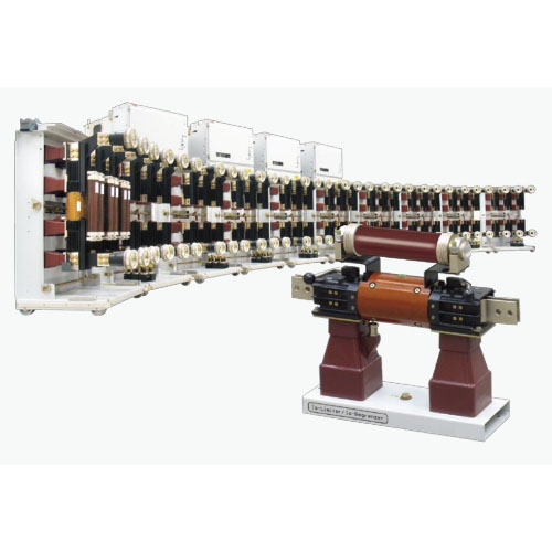
4.1 Overall Composition
Ang three-phase AC system fast current limiter ay binubuo ng:
4.2 Key Component Details
|
Component Name |
Composition / Features |
Key Parameters / Rules |
|
Conductive Bridge Base |
Includes mounting plate, insulators, pulse transformer, at connectors na may quick couplings |
- Rated current ≥2500A at voltage 12/17.5kV: Bolted connections. |
|
Conductive Bridge |
Conductive core at inductive filler encapsulated sa insulating cover |
Upon tripping, ang inductive filler ay triggered, driving ang conductive core to break rapidly sa pre-cut nito; ang current ay transfer sa parallel fuse. |
|
Matching Current Transformer |
Bushing o block type, series-connected sa main circuit |
Features a gapped core (high overcurrent factor, low remanence) at shielded primary/secondary windings (low impedance) upang ensure ang measurement accuracy at speed. |
|
Control Unit |
Includes power supply, control, indication, at anti-interference units |
- Dimensions: 600mm (W) × 1450mm (H) × 300mm (D); weight: 100kg. |
5.1 Core Composition
Ang device ay essentially an intelligent parallel combination ng dalawang components:
5.2 Operation Sequence
5.3 Auxiliary Units
6.1 Testing Requirements
Regular functional testing is required, which can be executed by users or ABB service engineers.
6.2 Dedicated Equipment
7.1 Supply Models
|
Model Type |
Applicable Scenarios |
Core Configuration |
|
Discrete Components |
For installation in existing switchgear |
3 bases + 3 conductive bridges + 3 CTs + 1 control unit |
|
Drawout Cabinet |
For metal-clad switchgear |
Conductive bridges mounted on withdrawable carts (with isolating switch function); CTs fixed; control unit installed in the low-voltage compartment |
|
Fixed Cabinet |
- For 12/17.5/24kV systems |
All components fixed inside the cabinet. For 36/40.5kV systems, the control unit is often installed in a separate control box. |
7.2 Key Technical Parameters (Example: Discrete Components)
Note: ¹ indicates forced air cooling is required; compatible with 50/60Hz frequency.
|
Technical Parameter |
Unit |
12kV |
17.5kV |
24kV |
36/40.5kV |
|
Rated Voltage |
V |
12000 |
17500 |
24000 |
36000/40500 |
|
Rated Current |
A |
1250-5000¹ |
1250-4000¹ |
2500-4000¹ |
1250-3000¹ |
|
Rated Short-Circuit Breaking Current (Max.) |
kA RMS |
210 |
210 |
210 |
140 |
|
Application Scenario |
Core Issue |
Solution Value |
|
Parallel System Operation |
Short-circuit current from multiple transformers in parallel exceeds switchgear ratings |
1. Allows reduced system impedance, minimizing voltage drop. |
|
Grid-Captive Power Interconnection |
Captive generator operation causes excessive short-circuit current at the common coupling point |
The only rational solution. Can be equipped with directional tripping (requires CT at generator neutral) to ensure operation only for grid-side faults. |
|
Bypassing Current-Limiting Reactors |
Reactors in continuous operation cause losses and voltage drop |
Bypasses reactors during normal operation (zero loss, zero voltage drop); rapidly interrupts during short circuits, diverting current to the reactor for limiting. |
|
Selective Application of Multiple Units |
Selective operation required when multiple limiters are installed on multi-section buses |
Uses "current vector sum" criterion to ensure only the limiter closest to the fault operates. Supports up to 5 transformers in parallel (using 4 limiters). |