Overview
Older distribution networks are primarily radial in structure, with most incoming and outgoing lines being overhead lines. The switching equipment typically consists of air-insulated vacuum circuit breakers or minimal-oil circuit breakers. These networks suffer from frequent faults, high operating costs, and prolonged, widespread power outages in the event of a failure, significantly hindering economic development.
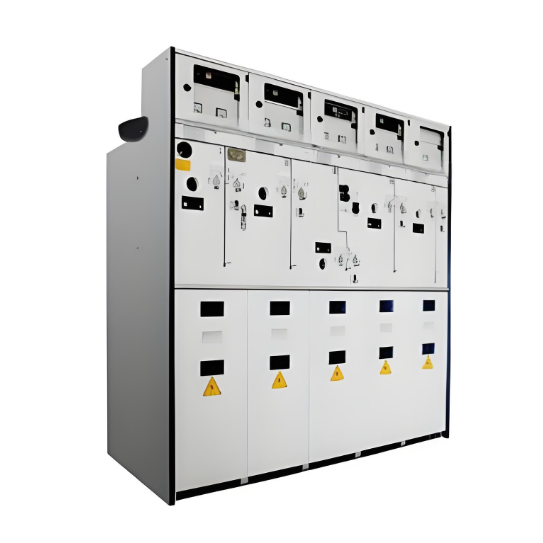
With rapid economic growth and the implementation of urban grid renovation, the demand for higher power supply reliability has increased. Fully insulated, fully sealed, maintenance-free, and compact SF₆ Ring Main Units (RMUs) have once again become a guarantee for reliable power supply.
1 Types and Structural Features of SF₆ RMUs
1.1 Types of SF₆ RMUs
SF₆ RMUs can be classified into two main types based on structure: Common Tank Type and Modular Unit Type. The early Common Tank Type RMUs typically featured one inlet, one loop, and one outlet, suitable for smaller loads. However, with increasing load demands, the expandable Modular Unit Type emerged, offering a maximum distribution capacity of up to 10 MVA.
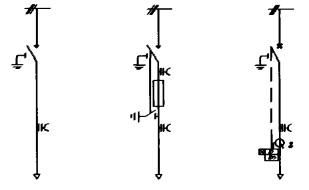
SF₆ RMUs can be categorized by function into Cable Type, Fuse Type, and SF₆ Circuit Breaker Type:
- Cable Type: Used for cable inlets/outlets. Rated current is 630A.
- Fuse Type: Can be directly connected to transformers. Rated current is 200A. However, considering the temperature rise effect of fuses, each RMU is practically limited to supplying transformers up to 1600 kVA in real-world applications.
- SF₆ Circuit Breaker Type: Used to protect transformers exceeding 1600 kVA. It can also serve as an incoming or bus section unit with overcurrent and instantaneous trip protection. Its rated current is 630A, with a total fault interruption time of 95ms.
The basic configurations of SF₆ RMUs are shown in the figure below.

1.2 Structural Features of SF₆ RMUs
The Common Tank Type SF₆ RMU generally consists of a gas tank, an operating mechanism compartment, and a cable connection compartment. The Modular Unit Type additionally requires a busbar connection compartment.
SF₆ RMUs have the following four major features:
- Gas Tank: This is the most critical part of the RMU. The gas tank contains the load switch, busbars, switch shaft, and SF₆ gas.
- The load switch is a 3-position switch, including an isolating knife switch and an arc chute.
- The moving contact of the knife switch has two special rivets made of Nichrome alloy, serving two purposes:
- Provides dry lubrication during switch opening/closing, ensuring the contact resistance between moving and fixed contacts does not increase after long-term use.
- Due to the high melting point of Nichrome alloy, the moving contact will not melt due to heat generated by short-circuit currents during closing or withstand periods.
- The arc chute contains deionizing plates which stretch the arc, reduce arc energy, and minimize the amount of metal vapor and SF₆ decomposition products generated when the load switch interrupts load current.
- The part of the busbar contacting the knife switch is the fixed contact. Besides meeting rated current capacity and dynamic/thermal stability requirements, the busbar design and manufacturing also consider electromagnetic field effects to minimize magnetic field impact.
- The switch shaft penetrates the gas tank and connects to the operating mechanism compartment, allowing operators outside the compartment to control the switch's closing, opening, and grounding states. A double-seal structure is used at the penetration point (the only moving connection between the tank and the outside), strictly ensuring the tank's airtightness during vacuum evacuation and gas filling.
- The annual leakage rate of SF₆ gas is only 0.0035%. This low leakage rate is crucial for the RMU's long-term safe operation.
- In addition to SF₆ gas for insulation and arc quenching, the gas tank also contains Aluminum Oxide (Al₂O₃), which accelerates SF₆ gas regeneration and acts as an excellent desiccant, maintaining SF₆ gas quality and minimizing arc faults. Should such a fault occur, an explosion-proof diaphragm below the tank protects personnel by venting hot gases directly into the cable trench beneath or behind the unit, away from operators at the front.
- The gas tank is constructed from 3mm thick stainless steel plate, double-sided welded.
- Operating Mechanism Compartment: The operating mechanism inside connects to the load switch and earthing switch via the switch shaft. Using an operating rod inserted into the operating hole, operators can easily perform closing, opening, and earthing operations with minimal effort (only 60 N·m required).
- Since the switch contacts are not visible, the operating mechanism features a position indicator directly linked to the switch shaft, clearly showing the current state of the load switch and earthing switch.
- Mechanical interlocks between the load switch, earthing switch, and front cover plate are installed, satisfying the five safety interlock requirements (anti-misoperation functions).
- Both the load switch and earthing switch are equipped with quick-make/quick-break mechanisms, ensuring opening/closing speeds are independent of the operator's speed.
- Switches with fuse protection (TS Type switchgear) also have an automatic trip device, available in mechanical or electrical versions. The mechanical trip principle: During a short-circuit fault in the unit's circuit, the fuse melts within the first half-cycle (~10ms) of the fault current. The fuse's striker pin impacts the trip mechanism, causing the load switch to open. The total fault interruption time is only 35ms, effectively protecting the unit and preventing fault propagation to adjacent units. Furthermore, due to excellent mechanical performance, the transfer current of Fuse Type switchgear can reach 2300A.
- Padlocks can be added to the operating levers on the front panel of the operating mechanism compartment to prevent unauthorized operation.
- For safe operation, a gas pressure gauge, directly connected to the gas tank and sealed against moisture (preventing fogging on the dial), is installed in the compartment, allowing maintenance personnel to accurately monitor the RMU's status at any time.
- A voltage indicator is also installed in the operating mechanism compartment, allowing operators to monitor circuit energization (neon bulb indicator) and verify phasing (using test sockets).
- Cable Connection Compartment: Located at the front of the RMU with a height of 1220mm, providing ample space for cable termination.
- Cable connections to the RMU's bushings use either Asbestos-free Touching Screened (AFTS) or Asbestos-free With Kit (AWK) silicone rubber cable accessories.
- Copper or aluminum cable cross-sections range from 25–240 mm² (for Fuse Type switchgear) or 35–400 mm² (for Cable Type switchgear).
- Busbar Connection Compartment (Modular Units): Positioned below the gas tank. Three bushings are arranged in a staggered "step-up" configuration, effectively minimizing space requirements and facilitating busbar connections.
- Bushings are hollow conductive type, allowing copper tube busbars to be directly bolted to the busbars inside the gas tank.
- Silicone rubber-insulated copper tube busbars are used, effectively increasing current-carrying capacity and reducing phase spacing (only 110mm).
- Connections between busbars and bushings use silicone rubber connectors (E-type terminal connectors and T-type extension connectors) and screw-on caps for electrically seamless connections directly on the bushings. These busbars withstand harsh conditions like moisture condensation, conductive dust, and salt deposits without failure.
- Additionally, the front of the busbar compartment is shielded by a separate grounded steel plate, separating it from the cable connection compartment.
2 Technical Parameters and Applications of SF₆ RMUs
2.1 Technical Parameters
|
Item
|
Cable-type Switchgear
|
Fuse-type Switchgear
|
Fuse-type Switch Cabinet
|
|
Rated Voltage / kV
|
12
|
12
|
12
|
|
Rated Current / A
|
630
|
200
|
630
|
|
Power-frequency Withstand Voltage / kV·min⁻¹
|
50 - 60
|
42 - 48
|
42 - 48
|
|
Impulse Withstand Voltage / kV
|
125 - 145
|
75 - 85
|
75 - 85
|
|
Rated Breaking Current / A
|
630
|
200
|
630
|
|
Rated Transfer Current / A
|
-
|
2300
|
-
|
|
Rated Short-circuit Breaking Current / kA
|
-
|
20
|
20
|
|
Breaking Capacitive Current / A
|
45
|
10
|
50
|
|
Breaking Inductive Current / A
|
16
|
16
|
-
|
|
Rated Peak Withstand Current / kA
|
50
|
-
|
50
|
|
Rated Short-time Withstand Current / kA·3s⁻¹
|
20
|
-
|
20
|
|
Rated Closing Current / kA
|
50
|
-
|
50
|
|
Number of Operations (630 A) / time
|
>100
|
>100
|
3000
|
|
Number of Closing Operations (50 kA) / time
|
5
|
5
|
5
|
|
Number of Mechanical Operations / time
|
2000
|
2000
|
4000
|
|
Ambient Temperature / °C
|
-
|
-25 - +55
|
-
|
|
Degree of Protection
|
IP65/IP4X
|
IP65/IP4X
|
IP65/IP4X
|
|
Leakage Rate / %, per year
|
-
|
0.0035
|
-
|
2.2 Applications of SF₆ RMUs
Due to their compact size, maintenance-free nature, and high reliability, SF₆ RMUs are particularly suitable for power distribution in critical facilities, high-rise buildings, residential complexes, and urban grids. They significantly reduce operating costs and footprint.
- 3-Unit Common Tank Type: Dimensions only 980mm × 635mm × 1050mm, making it ideal for kiosk transformers and outdoor applications.
- Modular Cable Type: Can incorporate switching tap-off boxes, supporting configurations up to one incoming and three outgoing feeders (i.e., incoming via the busbar compartment, with three outgoing feeders connected in parallel via the cable connection compartment).
- Modular Fuse Type: Suitable for locations far from substations where only one transformer is operating. To achieve local transformer control without needing an additional incoming unit, the incoming cable can be directly connected to the busbar compartment of a TS Type switchgear unit, providing the same functionality.
- Circuit Breaker Type Switchgear: Equipped with overcurrent and instantaneous trip protection. It can serve as a transformer protection unit, an incoming unit, or a busbar section unit. To enable remote tripping or tripping upon transformer gas protection relay operation (for Fuse Type switchgear), simply add an electromagnetic trip coil to the operating mechanism and provide a 220V AC or 24V DC power supply to the circuit.
Motorized Operation:
- For distribution automation, an electric motor can be added to the operating mechanism compartment, along with a 350mm high control box mounted on top. Local push-button operation (open/close) remains possible.
- Adding an Automatic Transfer Switch (ATS) device enables automatic switching between two incoming supplies, with or without a defined primary/standby configuration.
- Electric motors are typically available in various voltage levels (220V AC, 220V DC, 110V DC, 48V DC, 24V DC) for user selection.
- A short-circuit fault indicator can be installed on the front panel of the operating mechanism compartment, with signals transmitted to a remote control room. This indicator can be reset automatically, manually, or remotely.
- Low-voltage through-core Current Transformers (CTs) can be added to the cable connection compartment for current measurement.
- Surge arresters can also be installed within Cable Type switchgear units for RMU protection.
Distribution automation functions primarily focus on five areas: Data Acquisition, Monitoring & Control, Fault Isolation & Service Restoration, Geographic Information System (GIS), and Data Statistics & Reporting.
- Implementing distribution automation requires primary equipment to have motorized operating mechanisms and Feeder Terminal Units (FTUs) or Remote Terminal Units (RTUs).
- Fiber optic cable is the preferred communication medium. Communication protocols should be internationally recognized standards familiar to users, such as IEC 870, DNP 3.0, or TCP/IP.
- The control room SCADA software platform should be multi-tasking and multi-user capable, such as UNIX.
- The database is recommended to be stable with sufficient processing capacity, such as Oracle.
This solution is particularly suitable for RMUs located outdoors or far from low-voltage power sources, as it guarantees simultaneous operation of two 150W motors over 50 times.
3 Lifecycle
The lifespan of SF₆ RMUs is typically 25–30 years, and they can be conveniently retrofitted with distribution automation equipment. Therefore, SF₆ RMUs should be the preferred choice for urban grid renovation projects.


