| Brand | Rw Energy |
| Model NO. | Feeder Terminal Unit |
| Rated voltage | 230V ±20% |
| Rated frequency | 50/60Hz |
| Electric energy consumption | ≤5W |
| Series | RWK-55 |
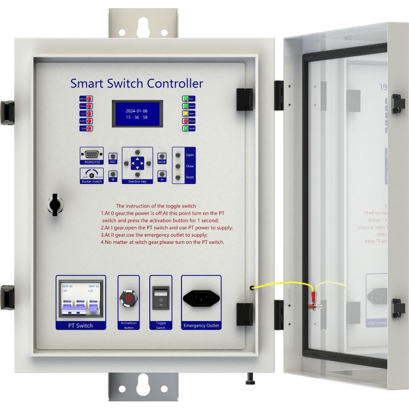
Description
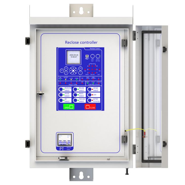
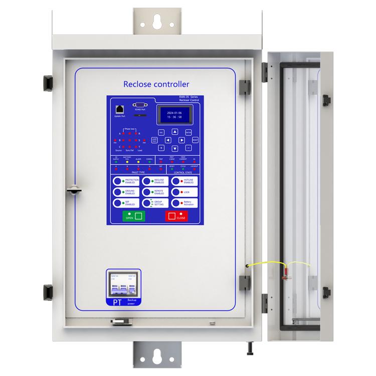
RWK-55 overhead line protection switch intelligent controller is medium voltage overhead line grid monitoring unit, it can be equipped with RCW(RVB) type vacuum circuit breaker for achieve of automatic monitoring, fault analysis and event records.
Its given to us a safety power grid for cutting line fault and automatic recovery operation and power automation.
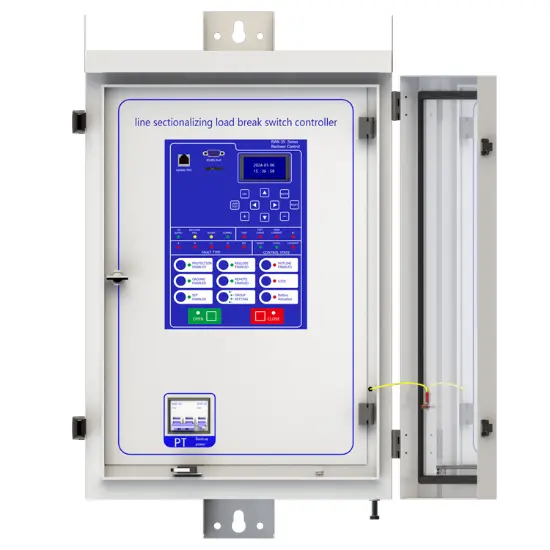
RWK-55 series is suitable for up to 35kV outdoor switchgear using, include: vacuum circuit breakers, oil circuit breakers and gas circuit breakers. RWK-55 intelligent controller is gathering with line protection, control, measurement and monitoring of voltage and current signals integrated automation and control devices outdoors.
RWK is an automatic management unit for single way/multi ways/ring network/two power sourcing, provided with all voltage and current signals and all functions. RWK-55 column switch intelligent controller supports: Wireless (GSM/GPRS/CDMA), Ethernet mode, WIFI, optical fiber, power line carrier, RS232/485, RJ45 and other forms of communication, and can access other station premises equipment (such as TTU, FTU, DTU, etc.).
Main function introduction
1. Protection relay functions:
1) 49 Thermal Overload,
2) 50 Three-section of Overcurrent (Ph.OC) ,
3) 50G/N/SEF Sensitive Earth Fault (SEF),
4) 27/59 Under/Over Voltage (Ph.OV/Ph.UV),
5) 51C Cold load pickup (Cold load).
2. Supervision functions:
1) 60CTS CT Supervision,
2) 60VTS VT Supervision,
3. Control functions:
1) 86 Lockout,
2) 79 Auto reclose,.
3) circuit-breaker control,
4. Monitoring Functions:
1) Primary currents for Phases and Zero sequence current,
2) Primary PT Voltage,
3) Frequency,
4) Binary Input/Output status,
5) Trip circuit healthy/failure,
6) Time and date,
7) Fault records,
8) Event records.
5. Communication functions:
a. Communication interface: RS485X1,RJ45X1
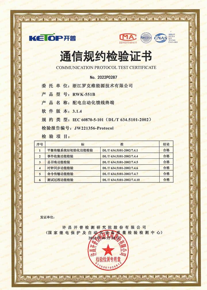
b. Communication protocol: IEC60870-5-101; IEC60870-5-104; DNP3.0; Modbus-RTU
c. PC software: RWK381HB-V2.1.3,The address of the information body can be edited and queried by PC software,
d. SCADA system: SCADA systems that support the four protocols shown in "b.”.
6. Data Storage functions:
1) Event Records,
2) Fault Records,
3) Measurands.
7. remote signaling remote measuring, remote controlling function can be customized address.
Technology parameters

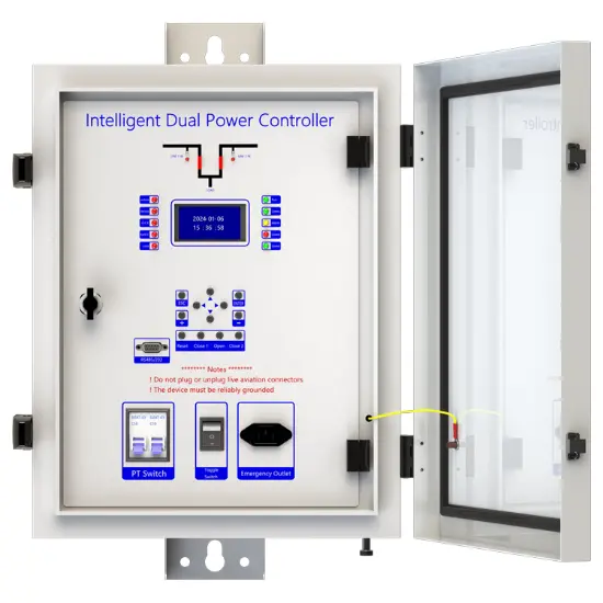
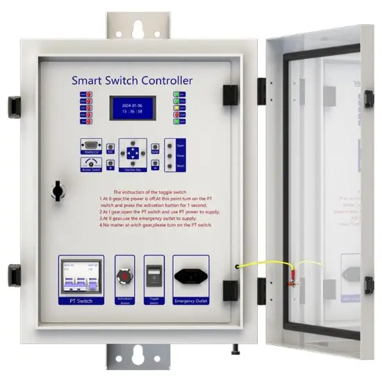
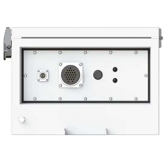
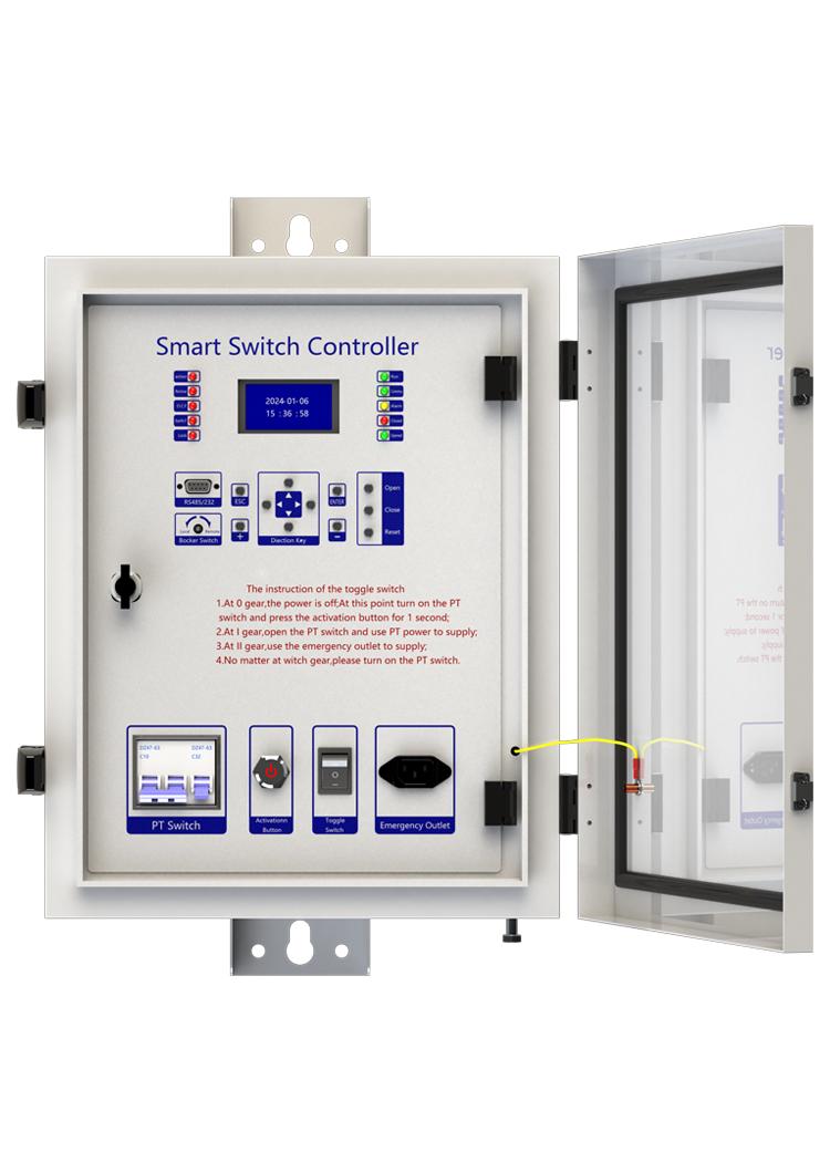
Device structure


About customization
The following optional functions are available: Power supply rated at 110V/60Hz,3 Voltage transform, 1 Zero phase sequence voltage sensor, cabinet heating defrosting device, 1 battery measurement, 1 battery activation management, GPRS communication module,1~2 signal indicators,1~4 protection pressure plates, the second voltage transformer, custom aviation socket signal definition.
For detailed customization, please contact the salesman.
Q: What does the line protection switch controller do?
A: It is mainly used to protect the line security. When the line is overloaded, short circuit and other abnormal conditions, the line protection switch controller can quickly detect these problems, and then automatically cut off the circuit, to prevent the line from being damaged by too much current, to avoid causing fire and other dangerous situations. Q: How does it detect a line anomaly?
A: It has a sophisticated current detection device inside. When the current in the line exceeds the set safe value, whether it is due to overload caused by too many appliances or short circuit caused by line fault, the detection device can sense the change in the current and trigger the controller action.
Q: Is the line protection switch controller durable?
A: Generally speaking, if it is a qualified product, it is more durable. The electronic components used are strictly screened, and the housing has good protection and can adapt to different environmental conditions, but it is also checked and maintained regularly to ensure that it works properly.

This device can connect to SCADA System and DMS, and you can connect the terminal to the server according to your local network conditions. This terminal supports CDMA (3G)/LTE (4G)/ NR(5G), ETH, fiber optic and other ways to access the network. You can also contact us directly, and we will provide you with a solution for distribution network automation.
Three-Section Overcurrent Protection is a coordinated protection scheme widely used in power systems to detect and isolate faults (e.g., short circuits) while ensuring selective tripping. It consists of three stages with distinct operating characteristics based on current magnitude and time delay:
Function: Responds immediately to severe overcurrents exceeding a high-set threshold (e.g., 5–10 times the rated current).
Purpose: Rapidly clears close-in faults (near the protection device) to prevent equipment damage.
Key Feature: No intentional time delay (operates in milliseconds).
Function: Triggers after a predefined short delay (e.g., 0.1–0.5 seconds) for moderate overcurrents (e.g., 2–5 times the rated current).
Purpose: Handles faults farther from the protection device, allowing downstream breakers to clear localized faults first (selectivity).
Coordination: Employs a time-graded scheme—higher fault currents (closer faults) trip faster, while lower currents (remote faults) trip slower.
Function: Activates after a longer time delay (e.g., several seconds) for low-magnitude overcurrents (e.g., 1.2–2 times the rated current).
Purpose: Serves as a backup for primary protection (Sections I/II) and addresses overloads or persistent faults.
Characteristic: May use an inverse-time curve (trip time decreases as current increases).
Coordination Principle
The three sections work hierarchically:
Section I clears severe faults instantly.
Section II handles moderate faults with short delays, prioritizing system selectivity.
Section III provides backup protection, ensuring reliability if upstream protections fail.
This layered approach minimizes outage scope, balances speed and selectivity, and enhances grid stability.
This protection device supports 2-channel serial data communication, RS232 or RS485 bus, independent of each other. It can be configured separately. The configuration method is as follows:
At this point, channel 1 has been established, and channel 2 is established in the same way as channel 1.
NOTE: 1. The product has been set to default settings before delivery to meet most usage scenarios. It is not recommended to make modifications or only modify controllable items (such as modifying communication protocols, configuring communication functions on/off, etc.) when it can be used normally