• Product
  • Suppliers
  • Manufacturers
  • Solutions
  • Free tools
  • Knowledges
  • Experts
  • Communities
Search


General Protection Device

  • General Protection Device

Key attributes

Brand RW Energy
Model NO. General Protection Device
Rated voltage 230V ±20%
Rated frequency 50/60Hz
Electric energy consumption ≤5W
Series RWH-15

Product descriptions from the supplier

Description

Description

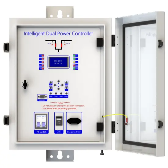
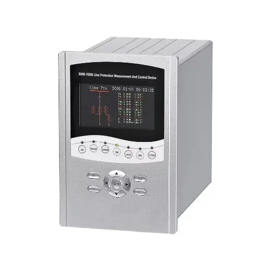
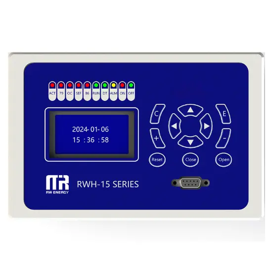
General Protection Device is a microprocessor as the core, combined with modern electronic technology, computer technology, communication technology, to realize the power system fault detection, protection control and operation monitoring function of intelligent equipment. As the key line of defense for the safe and stable operation of the power system, it replaces the traditional electromagnetic protection device and significantly improves the reliability, sensitivity and speed of protection.

The device is mainly composed of data acquisition system, microprocessor unit, input/output interface, communication module and power module. When working, the data acquisition system collects analog signals such as current and voltage in real time, and transmits them to the microprocessor after analog-to-digital conversion; the microprocessor analyzes and calculates the data according to preset protection algorithms and logic programs, and determines whether a fault or abnormality occurs in the power system; once a fault is detected, it quickly drives the circuit breaker to trip and removes the faulty equipment through the output interface and uploads the fault information to the monitoring center through the communication module. Upload the fault information to the monitoring center through the communication module

Support communication protocols: IEC 60870-5-101 IEC 60870-5-104 Modbus DNP3.0

Main function introduction

1. Protection relay functions:

1) 49 Thermal Overload,

2) 50 Three-section of Overcurrent (Ph.OC) ,

3) 50G/N/SEF Sensitive Earth Fault (SEF),

4) 27/59 Under/Over Voltage (Ph.OV/Ph.UV),

5) 51C Cold load pickup (Cold load).

2. Supervision functions: 

1) 60CTS CT Supervision,

2) 60VTS VT Supervision,

3. Control functions:

1) 86 Lockout,

2) 79 Auto reclose,.

3) circuit-breaker control,

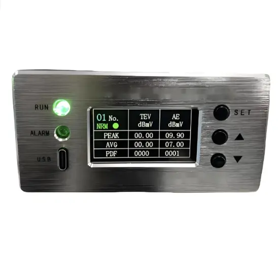
4. Monitoring Functions:

1) Primary currents for Phases and Zero sequence current,

2) Primary PT Voltage,

3) Frequency,

4) Binary Input/Output status,

5) Trip circuit healthy/failure,

6) Time and date, 

7) Fault records,

8) Event records.

5. Communication functions:

a.  Communication interface: RS485X1,RJ45X1

b. Communication protocol: IEC60870-5-101; IEC60870-5-104; DNP3.0;  Modbus-RTU

c. PC software: RWK381HB-V2.1.3,The address of the information body can be edited and queried by PC software,

d. SCADA system: SCADA systems that support the four protocols shown in "b.”.

6. Data Storage functions:

1) Event Records,

2) Fault Records,

3) Measurands.

7. remote signaling remote measuring, remote controlling function can be customized address.

Technology parameters

paramete.png

Device structure

RWH-15-Model.png

RWH-15端子定义图-Model.png

微机安装.png

About customization

The following optional functions are available: GPRS communication module. Upgrade SMS Function.

For detailed customization, please contact the salesman.


Q: What is the function of Microcomputer protection device?

A: The microcomputer protection device is mainly used to protect the electrical equipment in the switchgear. It can monitor electrical parameters such as current and voltage in real time. When there is overcurrent, overvoltage, undervoltage and other fault conditions, the rapid response, such as tripping to cut off the circuit, to prevent equipment damage, to ensure the safe and stable operation of the power system.

Q: What are its advantages over traditional protection devices?

A: The precision of The microcomputer protection device is higher, and the electric quantity can be measured accurately. It has the function of self-diagnosis, can find its own fault in time for maintenance. Moreover, the protection parameters can be set flexibly to adapt to different power system requirements. It can also realize remote communication and facilitate remote monitoring and operation, which is difficult to do with traditional protection devices.


Documentation Resource Library
Restricted
RWH-15 General Protection Device used manual
Operation manual
English
Consulting
Consulting
Certifcations
FAQ
Q: How should the communication function of this protective device be configured?
A:

This protection device supports 2-channel serial data communication, RS232 or RS485 bus, independent of each other. It can be configured separately. The configuration method is as follows:

  1. Enter the settings page: Edit → Para;
  2. Configure communication function on/off: Scroll down and find Comm1 Status set to 1, indicating it is turned on, and 0 indicates it is turned off. The default setting is open;
  3. Set communication baud rate: According to the baud rate configuration of RTU or protocol converter, the default value is 9600;
  4. Set communication protocol: There are four protocols to choose from, corresponding to setting 1 as IEC-60870-101, setting 2 as IEC-60870-104, setting 3 as DNP3.0, setting 4 as ModBus-RTU, default as IEC-60870-101;
  5. Set communication balance (only valid for multiple IEC-60870-101): Set 1 to IEC-60870-101 protocol balance mode and 0 to imbalance mode;
  6. Set the communication source address: Set the value to 1-65535, default value to 1;
  7. Set the target address for the report: set the value to 0-65535, default value to 1;
  8. Set active upload: 0 does not actively upload, 1 actively uploads, default value is 1;
  9. Save settings: After completing the settings, press the "Enter" key, enter the password 0099 (some models are 0077), press the "Enter" key again, and the screen will prompt "Save successful", indicating that the settings have been saved.

At this point, channel 1 has been established, and channel 2 is established in the same way as channel 1.

NOTE: 1. The product has been set to default settings before delivery to meet most usage scenarios. It is not recommended to make modifications or only modify controllable items (such as modifying communication protocols, configuring communication functions on/off, etc.) when it can be used normally

Q: Can this device be connected to SCADA System or DMS?
A:

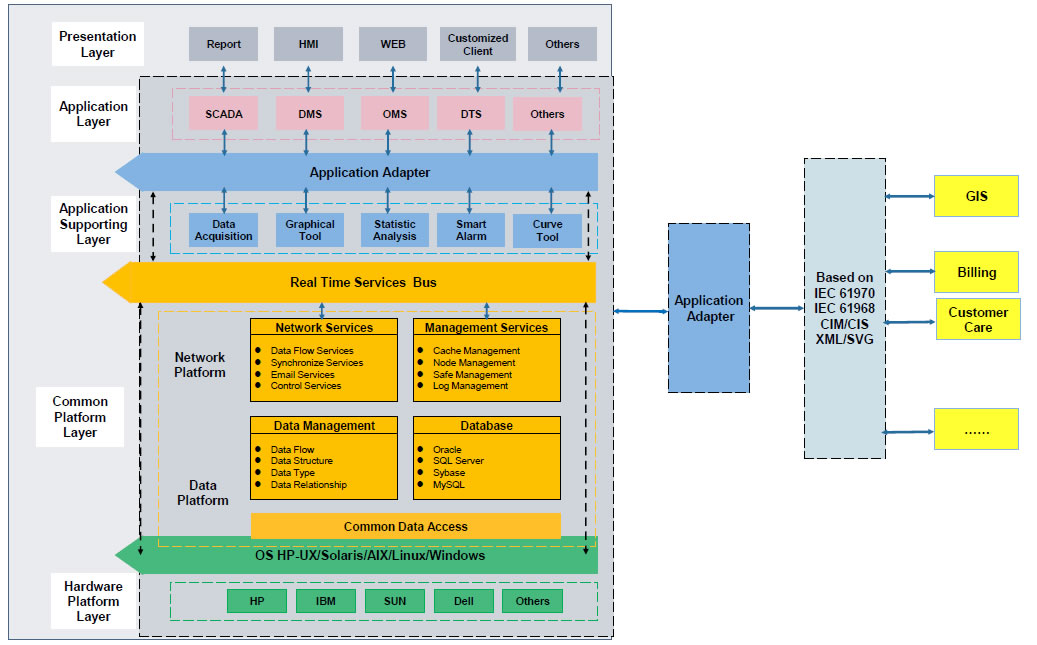
This device can connect to SCADA System and DMS, and you can connect the terminal to the server according to your local network conditions. This terminal supports CDMA (3G)/LTE (4G)/ NR(5G), ETH, fiber optic and other ways to access the network. You can also contact us directly, and we will provide you with a solution for distribution network automation.

Q: Does this device have corresponding upper computer software?
A:

Yes, this device has corresponding upper computer software (only available in windows-X86 version), which can be connected to the terminal through a serial port or network port, enabling fixed parameter configuration and viewing, address configuration for remote signaling, telemetry, and control, viewing of event reports, monitoring of electricity meters, packet capture of communication messages, and simulation of remote control functions.

Know your supplier
Online store
On-time delivery rate
Response time
100.0%
≤4h
Company overview
Workplace: 30000m² Total staff: Highest Annual Export(usD): 100000000
Workplace: 30000m²
Total staff:
Highest Annual Export(usD): 100000000
Services
Business Type: Design/Manufacture/Sales
Main Categories: High Voltage Electrical Apparatus/Low Voltage Electrical Apparatus/Instrument meters/New energy/Tester/Robot
Whole life care manager
Whole-life care management services for equipment procurement, use, maintenance, and after-sales, ensuring safe operation of electrical equipment, continuous control, and worry-free electricity consumption.
The equipment supplier has passed platform qualification certification and technical evaluation, ensuring compliance, professionalism, and reliability from the source.

Related Products

Related Knowledges

  • Impact of DC Bias in Transformers at Renewable Energy Stations Near UHVDC Grounding Electrodes
    Impact of DC Bias in Transformers at Renewable Energy Stations Near UHVDC Grounding ElectrodesWhen the grounding electrode of an Ultra-High-Voltage Direct Current (UHVDC) transmission system is located close to a renewable energy power station, the return current flowing through the earth can cause a rise in ground potential around the electrode area. This ground potential rise leads to a shift in the neutral-point potential of nearby power transformers, inducing DC bias (or DC offset) in their
    01/15/2026
  • HECI GCB for Generators – Fast SF6 Circuit Breaker
    1.Definition and Function1.1 Role of the Generator Circuit BreakerThe Generator Circuit Breaker (GCB) is a controllable disconnect point located between the generator and the step-up transformer, serving as an interface between the generator and the power grid. Its primary functions include isolating generator-side faults and enabling operational control during generator synchronization and grid connection. The operating principle of a GCB is not significantly different from that of a standard c
    01/06/2026
  • Distribution Equipment Transformer Testing, Inspection, and Maintenance
    1.Transformer Maintenance and Inspection Open the low-voltage (LV) circuit breaker of the transformer under maintenance, remove the control power fuse, and hang a “Do Not Close” warning sign on the switch handle. Open the high-voltage (HV) circuit breaker of the transformer under maintenance, close the grounding switch, fully discharge the transformer, lock the HV switchgear, and hang a “Do Not Close” warning sign on the switch handle. For dry-type transformer maintenance: first clean the porcel
    12/25/2025
  • How to Test Insulation Resistance of Distribution Transformers
    In practical work, insulation resistance of distribution transformers is generally measured twice: the insulation resistance between thehigh-voltage (HV) windingand thelow-voltage (LV) winding plus the transformer tank, and the insulation resistance between theLV windingand theHV winding plus the transformer tank.If both measurements yield acceptable values, it indicates that the insulation among the HV winding, LV winding, and transformer tank is qualified. If either measurement fails, pairwise
    12/25/2025
  • Design Principles for Pole-Mounted Distribution Transformers
    Design Principles for Pole-Mounted Distribution Transformers(1) Location and Layout PrinciplesPole-mounted transformer platforms should be located near the load center or close to critical loads, following the principle of “small capacity, multiple locations” to facilitate equipment replacement and maintenance. For residential power supply, three-phase transformers may be installed nearby based on current demand and future growth projections.(2) Capacity Selection for Three-Phase Pole-Mounted Tr
    12/25/2025
  • Transformer Noise Control Solutions for Different Installations
    1.Noise Mitigation for Ground-Level Independent Transformer RoomsMitigation Strategy:First, conduct a power-off inspection and maintenance of the transformer, including replacing aged insulating oil, checking and tightening all fasteners, and cleaning dust from the unit.Second, reinforce the transformer foundation or install vibration isolation devices—such as rubber pads or spring isolators—selected based on the severity of vibration.Finally, strengthen sound insulation at weak points of the ro
    12/25/2025

Related Solutions

  • Distribution automation systems solutions
    What are the difficulties in overhead line operation and maintenance?Difficulty one:Overhead lines of distribution network have wide coverage,complicatedterrain,many radiation branches and distributed power supply,resultingin "many line faults and difficulty in fault troubleshooting".Difficulty Two:Manual troubleshooting is time-consuming and laborious.Meanwhile,therunning current,voltage and switching state of the line cannot be graspedin real time,because of the lack of intelligent technical m
    04/22/2025
  • RW8000 DMS Distribution Management System Solutions
    OverviewNowadays, the development trend of power grid is intellectualization. As an important part of power grid, the power distribution system is very close to the customers and it has to run properly. The distribution management system (DMS)played an important role in it.Introduction:RW8000 power distribution management system (DMS) is designed for the smart grids. It is based on real-time application, centered on distribution network operation and management, focusing on the business process
    09/07/2023
  • High-Precision Electrical Parameter Monitoring System Solution
    1.Introduction​With the increasingly stringent requirements for power supply quality in high-end facilities such as precision manufacturing, medical diagnosis, and data centers, traditional power monitoring systems, due to their low sampling accuracy and weak data analysis capabilities, can no longer meet the demand for deep insight and precise management of power quality. In response, we are introducing a new generation ​High-Precision Electrical Parameter Monitoring System. With ​millisecond-l
    09/28/2025
Haven't found the right supplier yet? Let matching verified suppliers find you. Get Quotation Now
Haven't found the right supplier yet? Let matching verified suppliers find you.
Get Quotation Now
Send inquiry
+86
Click to upload file

IEE Business will not sell or share your personal information.

Download
Get the IEE Business Application
Use the IEE-Business app to find equipment, obtain solutions, connect with experts, and participate in industry collaboration anytime, anywhere—fully supporting the development of your power projects and business.