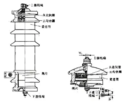
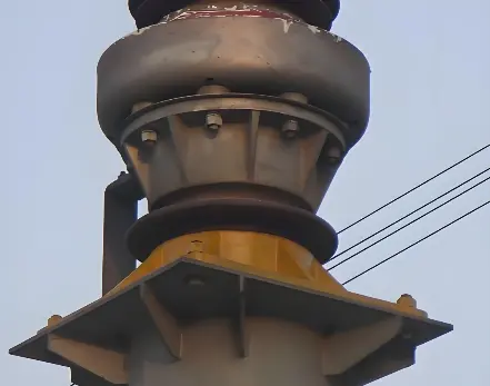
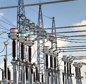
Learn common surge arrester faults, their causes, and handling principles – a practical guide for reliable overvoltage protection.
Safety Notice: This document is for knowledge learning and O&M reference only and does not constitute on-site operating instructions. When de-energisation, isolation, maintenance, testing, or fault handling are involved, the site procedures, safety measures, and approval processes of the responsible unit must be strictly followed.
Leakage current is the core indicator reflecting the internal valve disc condition. Under normal operation, the arrester passes only microampere-level leakage current at power frequency. Abnormal changes in leakage current often indicate internal defects.
Leakage current criteria are classified into three severity levels with corresponding handling requirements:
→ Action: Strengthen monitoring, shorten patrol interval, arrange offline test if necessary
→ Action: Register as serious defect, report to dispatch and maintenance, arrange offline inspection ASAP
→ Action: Immediately report to dispatch, apply for out-of-service handling
Under normal operation arrester heating is minimal. When internal valve discs age or become damp, power loss increases significantly, manifesting as abnormal temperature rise.
Infrared detection criteria in three severity levels:

External insulation is the first line of defence against environmental attack; damage directly affects safe operation.
Classified by crack severity:
Most severe fault form; often accompanied by system protection operation; requires emergency handling.
Seal failure is the primary cause of internal moisture; insulation performance and electrical characteristics severely degrade after moisture ingress.

Earthing system reliability directly affects arrester protection effectiveness and personnel safety.

Arresters should have no abnormal sounds under normal power frequency voltage; any abnormal sound indicates possible serious internal defect.
| Patrol Type | Main Content |
|---|---|
| Routine patrol | Check leads, joints, grading rings, porcelain, seals, earthing downleads, monitoring devices, discharge counters |
| Post-thunderstorm special patrol | Check counter operation records, surface discharge/flashover traces, lead connections |
| Post-high-wind/sandstorm | Check lead connections, vertical arrester sway |
| Fog/haze weather | Focus on porcelain contamination and corona discharge |
| Ice accretion weather | Check external insulation ice accretion and icicle bridging |
| Heavy snow | Promptly clear lead snow accumulation and icicles |
| Test Item | Applicable Type | Criteria |
|---|---|---|
| Insulation Resistance | ≥ 35 kV arresters | General: < 2500 MΩ = abnormal; absorption ratio K = R60s/R15s < 1.3 = abnormal. DFS type etc. with special requirements: per equipment technical documentation |
| Leakage Current | FZ type | Conductive current > 0.6 mA or significant increase vs. previous = abnormal |
| Leakage Current | Other types | Per equipment technical documentation and test procedures |
| Reference Voltage | ≥ 110 kV | Drop > 10% vs. initial/specified value; if confirmed ageing → recommend retirement |
| DC Reference Voltage Deviation | All types | Deviation within ±5% |
| Reference Voltage | All types | Power frequency & DC reference voltages per product technical conditions; allowable deviation vs. manufacturer measured values per relevant standards |
| Dielectric Loss Factor | All types | tanδ < 0.05; increases significantly when damp |
| Test Cycle | All types | Per site operating procedures and preventive test procedures |
| Voltage Level | Detection Cycle |
|---|---|
| All voltage levels | Per site operating procedures and infrared detection technical specifications |
| Newly installed & after A/B class overhaul re-energisation | Per relevant procedures within specified time for precise measurement |

Upon discovering abnormality, first judge whether safety is endangered:
Login