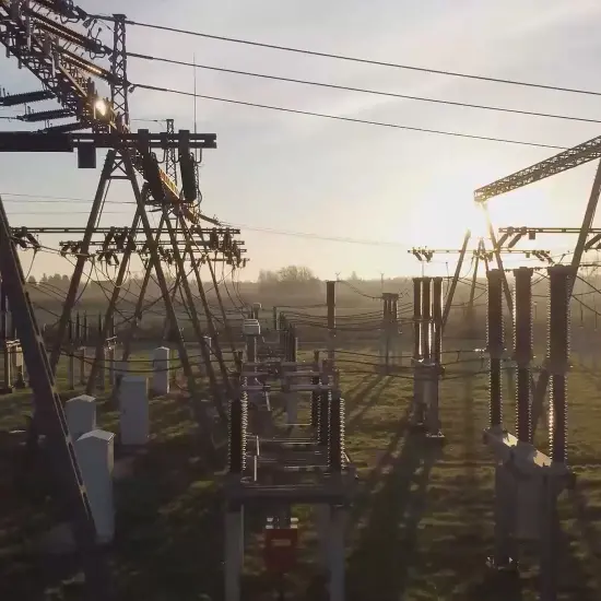
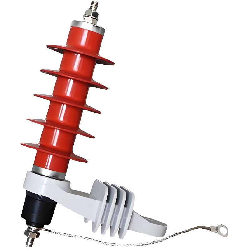
As a senior expert in high-voltage engineering and power grid protection, I will provide a deep technical dive into the logic of surge arrester selection and the physical constraints that define the 550kV engineering ceiling.
In high-voltage engineering, a surge arrester is not merely a component; it is a high-speed "pressure relief valve" for electromagnetic energy. Its selection is a critical balance between system reliability and equipment insulation safety.
1. The Core Selection Logic: The Three-Pillar Framework
Selecting a surge arrester requires precise alignment with the system's thermal and dielectric limits. We focus on three critical parameters:
- Continuous Operating Voltage (UcUc / MCOV): This is the maximum RMS power-frequency voltage that the arrester can withstand indefinitely. It must be higher than the system's highest phase-to-ground voltage. If UcUc is selected too low, the Zinc Oxide (ZnO) varistors will experience excessive leakage current, leading to thermal runaway and catastrophic failure.
- Rated Voltage (UrUr): This defines the arrester’s ability to "reseal" or recover after a discharge event. It is typically calculated based on the maximum Temporary Overvoltage (TOV) the system might experience during a ground fault or load shedding.
- Protection Level (Residual Voltage): When a lightning or switching surge strikes, the arrester clamps the voltage. The resulting "Residual Voltage" must be significantly lower than the Basic Insulation Level (BIL/LIWL) of the protected equipment (like a power transformer). We typically demand a safety margin of at least 20% to 25%.
2. Physical Length vs. Voltage: The Law of Proportionality
The physical height of a surge arrester is dictated by two non-negotiable laws of physics:
- Internal ZnO Stacking: The non-linear ZnO varistor discs are the heart of the device. Since each disc has a specific voltage rating (e.g., a few kV per cm), higher system voltages require a taller stack of discs to prevent conduction during normal operation.
- External Creepage and Flashover: The outer housing (Porcelain or Silicone Rubber) must be long enough to prevent "flashover"—where electricity jumps along the surface of the insulator. In 500kV systems, the Creepage Distance (the path length for surface leakage) can exceed 15-20 meters to account for pollution and humidity, necessitating a very tall physical structure.
3. Decoding the 550kV Ceiling: Why the Limit?
In the industry, 550kV is often cited as the "limit" for standard EHV (Extra-High Voltage) arrester catalogs. This is due to several engineering bottlenecks:
- Standardized System Max (UmUm): For a nominal 500kV AC grid, the international standard (IEC/ANSI) defines the Maximum Equipment Voltage (UmUm) as 550kV. Therefore, 550kV is the design benchmark for the highest tier of Extra-High Voltage equipment.
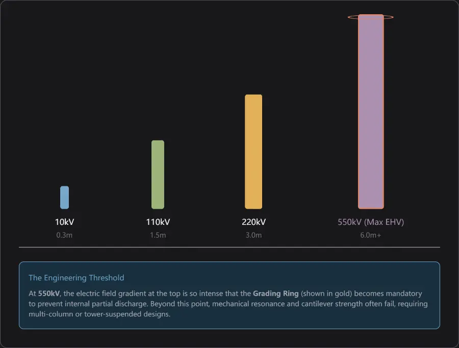
- Mechanical Stability & Aspect Ratio: A 550kV arrester typically stands between 5 to 6 meters tall. At this height, the device becomes a "thin pillar." Wind loads and seismic forces create massive bending moments at the base. Going beyond 550kV (e.g., to 750kV or 1000kV) makes the single-column structure mechanically unstable and prone to snapping.
- Electric Field Grading: As the arrester grows taller, the electric field distribution becomes highly non-uniform. The top sections bear a disproportionate amount of voltage stress. To fix this, we use massive Grading Rings to force the electric field to spread evenly across the stack. Beyond 550kV, the required grading rings become so large that they interfere with other substation equipment clearances.
- The Shift to UHV (Ultra-High Voltage): For 800kV DC or 1000kV AC, we no longer use simple pillars. We shift to Multi-column parallel structures or Tower-supported suspended arresters. These are specialized engineering feats rather than "off-the-shelf" products.
The following visualization illustrates the structural complexity and the role of the grading ring in a 550kV unit compared to lower voltage levels.
Summary for your records:
- Selection: Driven by MCOV (UcUc), Rated Voltage (UrUr), and Residual Voltage vs. BIL.
- Height: Proportional to voltage due to internal ZnO disc stacking and external creepage requirements.
- The 550kV Limit: It represents the standard "Top-of-Class" for AC 500kV Extra-High Voltage grids. Engineering past this point moves from "standard components" into "custom UHV infrastructure" territory where mechanical and field-grading constraints dominate the design.
Contact us:
Edited From:Dyson

 Login
Login