How to Improve Rectifier Transformer Efficiency? Key Tips

Optimization Measures for Rectifier System Efficiency

Rectifier systems involve numerous and diverse equipment, so many factors affect their efficiency. Therefore, a comprehensive approach is essential during design.
Increase Transmission Voltage for Rectifier Loads
Rectifier installations are high-power AC/DC conversion systems requiring substantial power. Transmission losses directly impact rectifier efficiency. Increasing the transmission voltage appropriately reduces line losses and improves rectification efficiency. Generally, for plants producing less than 60,000 tons of caustic soda annually, 10 kV transmission is recommended (avoiding 6 kV). For plants above 60,000 tons/year, 35 kV transmission should be used. For plants exceeding 120,000 tons/year, 110 kV or higher voltage transmission is required.Use Direct-Step-Down Rectifier Transformers
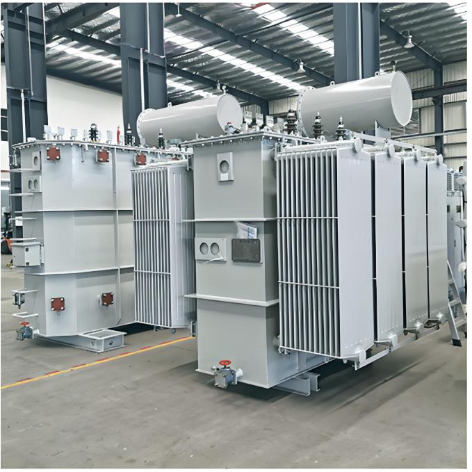
Similar to transmission principles, the primary (network) voltage of the rectifier transformer should match the transmission voltage. A higher direct step-down voltage means lower current in the high-voltage winding, resulting in lower heat losses and higher transformer efficiency. Where possible, use higher transmission voltages and direct-step-down rectifier transformers.Minimize the Tap-Changing Range of the Rectifier Transformer
The tap-changing range significantly impacts transformer efficiency; a smaller range yields higher efficiency. Blindly increasing the range (e.g., to 30%-105%) for ease of phased commissioning is inadvisable. After full production, transformers typically operate at 80%-100%, leaving extra tap windings causing permanent losses. A range of 70%-105% is suitable. Combining high-voltage star-delta switching and thyristor voltage regulation can further reduce this to 80%-100%, markedly improving efficiency.Use Oil-Immersed Self-Cooled Rectifier Transformers
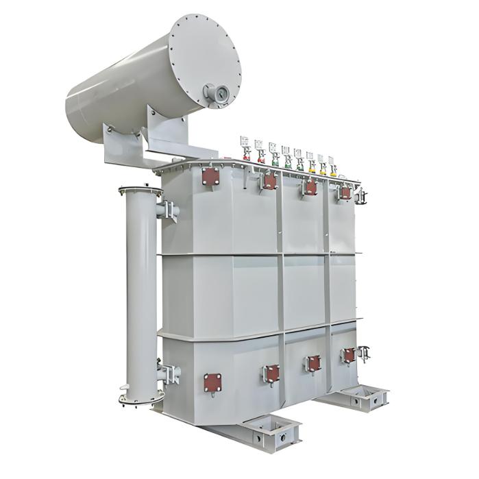
Using oil-immersed self-cooled transformers saves the electrical energy consumed by fans. Although manufacturers often design large-capacity transformers with forced oil-air cooling, the cooling radiators can simply be enlarged. Combined with open-air installation to enhance heat dissipation, the transformer's operation remains reliable without forced cooling.Adopt "Planar Integrated" Installation for Rectifier Equipment
Installing the rectifier transformer, rectifier cabinet, and electrolyzer in a "planar integrated" manner minimizes the length of AC/DC busbars, reducing resistive losses and improving system efficiency. Specifically, place all three units on the same level and as close together as possible, forming a compact unit. Connect the transformer's side output to the rectifier cabinet with busbars under 1.2 meters long, and route the cabinet's bottom output directly to the electrolyzer via underground busbars.Avoid Flexible Connections for Busbar Installation
The "planar integrated" layout results in short busbar connections between the transformer and cabinet, and across DC knife switches, minimizing thermal expansion. Rigid connections are sufficient, ensuring safety while eliminating the losses associated with flexible connectors and their additional joints, thus improving efficiency.Use a Lower Busbar Current Density
The economic current density for AC/DC busbars is 1.2–1.5 A/mm². Selecting a lower density (1.2 A/mm², or even 1.0 A/mm²) optimizes energy savings.Use Busbars with a Height-to-Width Ratio Greater Than 12
Busbars with a height-to-width ratio exceeding 12 have a larger surface area for heat dissipation, resulting in lower operating temperatures, better conductivity, lower resistive losses, and higher unit efficiency.Apply Vaseline to Busbar Compression Joints
Ensure adequate contact area at busbar joints (keeping current density below 0.1 A/mm²), and maintain a flat, smooth surface. Apply vaseline to prevent copper oxidation and poor contact, which increases power loss. Do not use conductive grease, as its oil base evaporates at high temperatures, causing the semi-metallic compound to harden and lose conductivity, leading to additional heating.Select Silicon Rectifier Cabinets Appropriately
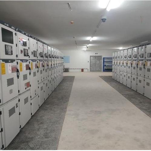
Silicon diode rectifier cabinets are 3–4% more efficient than thyristor cabinets. When multiple rectifier cabinets operate in parallel, incorporating one silicon cabinet can further reduce consumption and improve efficiency.Use Rectifier Cabinets with High-Current Devices
Using 2–3 high-current devices per bridge arm improves current sharing, reduces device power losses, and increases rectification efficiency.Adopt Numerical Control (NC) Rectifier Control Cabinets
NC control enables more precise rectifier triggering, smaller DC voltage ripple, and higher DC current stability. This benefits electrolyzer operation and improves electrolysis efficiency.Operate Thyristors in Full Conduction Mode
During operation, keep the thyristor's firing angle below 10° to maintain near-full conduction. This minimizes the thyristor rectifier's internal losses and maximizes its efficiency.Reduce the Thyristor Rectifier Cabinet's Margin Angle
The margin angle (overlap angle) is closely related to the rectifier system's natural power factor. A smaller margin angle results in a higher power factor (especially when the firing angle α is small). During commissioning, minimize the margin angle while ensuring reliable operation. A small α keeps the thyristors near full conduction.Use Two or More Rectifier Transformers in Parallel
For high-power DC loads, use two or more rectifier transformers in parallel. This reduces the equivalent reactance and the circulating current during transformer transfer, decreasing total losses and improving efficiency.Use DC Knife Switches with Higher Rated Currents
DC knife switches generate significant heat under full load. Selecting a switch with a rated current one grade higher provides energy savings. For example, use a 31,500 A switch for a 25,000 A load, or a 40,000 A switch for a 30,000 A load.Use Energy-Efficient Large DC Current Sensors
Some large DC sensors require an AC power supply for zero-flux comparison, consuming additional energy. Hall-effect sensors are preferable; they directly output a 0–1 V DC signal to the display instrument without consuming extra power.Design for Multi-Phase Rectification
Use multi-phase rectification where possible. Employ 6-pulse rectification (three-phase bridge or dual reverse-star with balancing reactor, both in co-phase inverse parallel) on single transformers. For two or more transformers, use equivalent 12-pulse or 18-pulse rectification. This effectively suppresses low-order harmonics, improving rectifier efficiency.