
Babban karamin karkarfi ba za su iya kofar da zama zuwa busbars na yau, domin an yi waɗanda ya haɗa jiki mai sarrafa (EMF) shi ne zero a cikin lokacin, wanda yake taimaka da girmamawa. An samun hanyoyin kofar da alƙakalƙan a kan abin da ake amfani da su don bincike, mataki amsa a kan alternator ko a kan bus da yake mafi girma.
Kofar da Synchronising Lamps
Za su iya amfani da sassa uku na synchronizing don tabbatar da yanayin kofar ko kofar da wani makina. An nuna hakan da ake amfani da ita, ɗaya daga cikinsu ita ce metoda na dark lamp—wanda ake amfani da voltmeter don kofar—ta haka. Hakan ya fi kyau wa makinas na kusa.
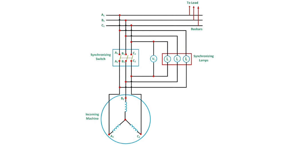
Yadda Ake Kofar Da Amfani Da Synchronizing Lamps
Prime Mover and Voltage Adjustment
Bidda prime mover na makina na kofar kai tsaye kuma fadada shi har zuwa birnin da ake magana a kan.
Sakata current na field na makina na kofar har zuwa lokacin da output voltage ta kafin da bus voltage.
Frequency and Phase Detection
Sassan uku na synchronizing za su iya jirgin da kowane shekaru a cikin taron da ke nuna farkon frequency bayan makina na kofar da bus.
Phase Sequence Check: Idan sassan uku sun ji masu zaman lafiya da kullum, zan tabbatar da phase connections sun fi kyau. Ba haka, akwai cutarwa a kan phase sequence.
Corrective Actions and Switch Closure
Don kore phase sequence, interchange any two line leads of the incoming machine.
Fine-tune the incoming machine’s frequency until the lamps flicker at a rate of less than one dark period per second.
After final voltage adjustment, close the synchronizing switch at the midpoint of the dark period to minimize voltage discrepancy.
Advantages of the Dark Lamp Method
Disadvantages of the Dark Lamp Method
Three Bright Lamp Method
Two Bright One Dark Lamp Method
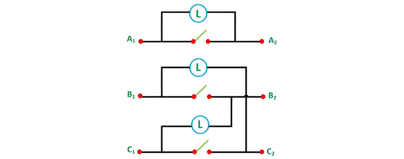
Connection Configuration and Synchronization Steps
In this setup, A1 is connected to A2, B1 to C2, and C1 to B2. The prime mover of the incoming machine is started and accelerated to its rated speed. The excitation of the incoming machine is adjusted such that the induced voltages EA1, EB2, EC3 match the busbar voltages VA1, VB1, VC1. The corresponding diagram is illustrated below.
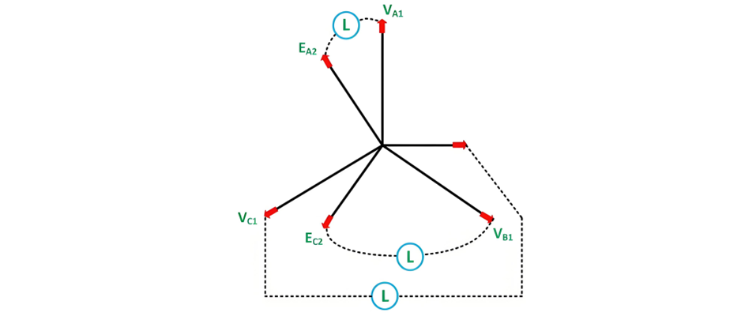
Optimal Switch Closure and Phase Sequence Verification
The ideal moment to close the synchronizing switch occurs when the directly connected lamp (A1-A2) is fully dark while the cross-connected lamps (B1-C2, C1-B2) are equally bright. If the phase sequence is incorrect, this condition will not be met, and all lamps will either remain dark or flicker out of sync.
To correct the phase sequence, swap any two line connections of the incoming machine. Since the dark range of incandescent lamps spans a significant voltage interval (typically 40-60% of rated voltage), a voltmeter (V1) is connected across the directly connected lamp. The switch should be closed when the voltmeter reads zero, indicating minimal voltage difference between the incoming machine and the busbar.
Operational Modes and Automation
Once synchronized, the incoming machine "floats" on the busbar and can begin delivering power as a generator. If the prime mover is disengaged while connected, the machine will operate as a motor, drawing power from the grid.


