
Jieneratorê statîk nayê bi çubên dawiyê piştgirî bibe, di demê ku hêza electromotiv (EMF) li ser asta yekem yên din de sifir e, ev short circuitê pê bike. Prosedûyê synchronization û taybetmendiyên bikaranîn ê ji bo kontrolkirina we dike, heta yek alternator bi yek alternator din yê din yekan bibe an alternator bi busê bêhêman bibe.
Synchronization via Synchronising Lamps
Setî ya sê synchronizing lamps bikar bînin ji bo verifikasyonê şertên ji bo paralleling an synchronization machineyê nû bi yekê din. Yekana dark lamp method—ji bo synchronization bi veymetre—li jêr hatine ilustrandin. Ev yekana ji bo makinalên ku guçê nekîn uştê ye.
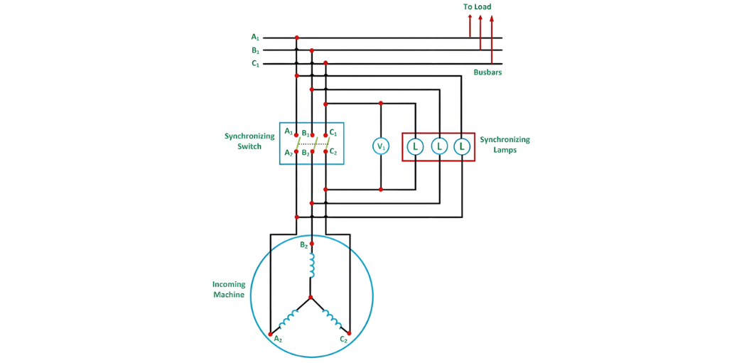
Synchronization Process Using Synchronizing Lamps
Prime Mover and Voltage Adjustment
Prime moverê ji machineyê nû dest pêbike û bi zelî derbas bikin tu heta lêzêna rating ê.
Currentê fieldê ji machineyê nû tevahî bike heta voltageyê outputê wê bi voltageyê busê yek bibe.
Frequency and Phase Detection
Sê synchronizing lamps hatine flicker bikin bi reyê proporsional ê ji bo feraqê frequency ê di machineyê nû û bus de.
Phase Sequence Check: Eger hemî lamps bi xwe rojname û dim bike, phase connections ê rast in. Eger na, phase sequence ê misaligned e.
Corrective Actions and Switch Closure
Ji bo rectifying phase sequence, her du line leads ê ji machineyê nû biyînin.
Fine-tune frequency ê ji machineyê nû heta lamps flicker bikin bi reyê min ji yek dark period per second.
Pas voltage adjustment ê final, switch ê synchronization bi ser midpoint ê dark period bicerbikin ji bo minimize voltage discrepancy.
Advantages of the Dark Lamp Method
Disadvantages of the Dark Lamp Method
Three Bright Lamp Method
Two Bright One Dark Lamp Method
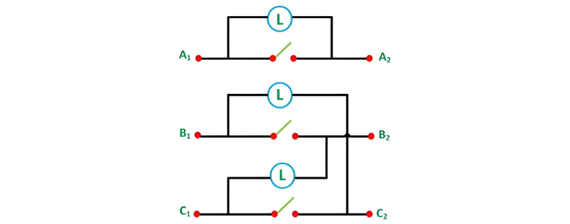
Connection Configuration and Synchronization Steps
In this setup, A1 is connected to A2, B1 to C2, and C1 to B2. The prime mover of the incoming machine is started and accelerated to its rated speed. The excitation of the incoming machine is adjusted such that the induced voltages EA1, EB2, EC3 match the busbar voltages VA1, VB1, VC1. The corresponding diagram is illustrated below.
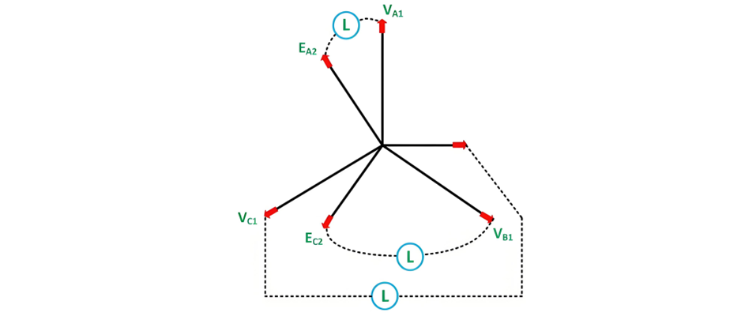
Optimal Switch Closure and Phase Sequence Verification
The ideal moment to close the synchronizing switch occurs when the directly connected lamp (A1-A2) is fully dark while the cross-connected lamps (B1-C2, C1-B2) are equally bright. If the phase sequence is incorrect, this condition will not be met, and all lamps will either remain dark or flicker out of sync.
To correct the phase sequence, swap any two line connections of the incoming machine. Since the dark range of incandescent lamps spans a significant voltage interval (typically 40-60% of rated voltage), a voltmeter (V1) is connected across the directly connected lamp. The switch should be closed when the voltmeter reads zero, indicating minimal voltage difference between the incoming machine and the busbar.
Operational Modes and Automation
Once synchronized, the incoming machine "floats" on the busbar and can begin delivering power as a generator. If the prime mover is disengaged while connected, the machine will operate as a motor, drawing power from the grid.


