• Product
  • Suppliers
  • Manufacturers
  • Solutions
  • Free tools
  • Knowledges
  • Experts
  • Communities
Search


Grounding Causes of Cable Lines and the Principles of Incident Handling

Felix Spark
Felix Spark
Field: Failure and maintenance
China

Our 220 kV substation is located far from the urban center in a remote area, surrounded primarily by industrial zones such as Lanshan, Hebin, and Tasha Industrial Parks. Major high-load consumers in these zones—including silicon carbide, ferroalloy, and calcium carbide plants—account for approximately 83.87% of our bureau’s total load. The substation operates at voltage levels of 220 kV, 110 kV, and 35 kV.

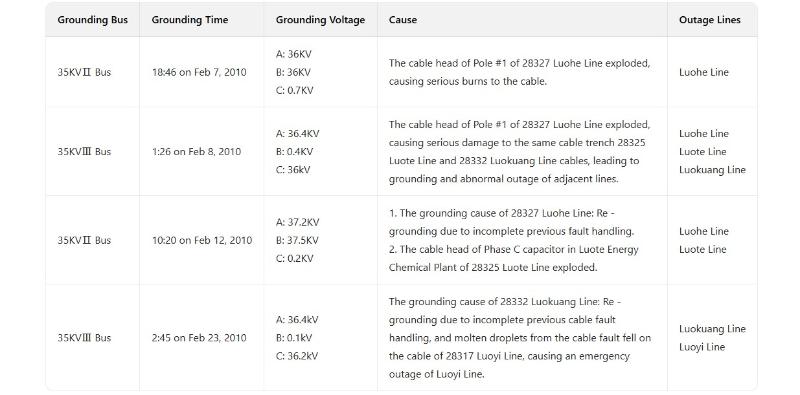
The 35 kV low-voltage side mainly supplies feeders to ferroalloy and silicon carbide plants. These energy-intensive factories are built close to the substation, resulting in heavy loads, short feeder lines, and severe pollution. These feeders are predominantly connected via cables, sharing a common cable trench. Therefore, any line fault poses significant risks to the substation. This paper analyzes the causes of 35 kV line faults and discusses corresponding countermeasures. In February 2010, a 220 kV substation under our bureau frequently experienced grounding faults on the 35 kV II bus and 35 kV III bus, as detailed in Table 1.

fault.jpg

1 Analysis of Grounding Causes in Cable Lines
According to our bureau’s 2010 statistics on cable incidents, the main causes of cable line failures were as follows:

  • Temperature effects: At facilities such as Sanyou Chemical, high temperatures in furnace transformers and cable terminations led to insulation breakdown. This occurred in approximately 18 incidents, requiring the fabrication of 15 cable terminations.

  • High cable density in cable trenches: At Rongsheng Yinbei Ferroalloy Plant, manhole covers fell and damaged cables in the trench, causing short circuits and fires that affected other plants’ cables. A total of 51 cable splices were made.

  • Severe customer overloading: Plants such as Huanghe Ferroalloy, Pengsheng Metallurgy, Lingyun Chemical, and Rongsheng Yinbei Ferroalloy operated cables under long-term overload conditions, accelerating cable aging and increasing temperatures. Especially during hot summers, thermal stress caused insulation breakdown in cables and terminations, requiring approximately 50 cable terminations.

  • Mechanical damage: Excavators during construction and earthworks severed cables, causing fractures and insulation damage. A total of 25 cable terminations and splices were made.

  • Cable quality issues: Defects such as air bubbles in insulation or broken shielding during manufacturing led to 9 accidents, requiring 9 cable terminations and splices.

  • Damage during cable laying: Excessive pulling tension due to long cable runs caused scraping by sharp objects, resulting in 13 cable damage incidents.

  • Poor cable termination workmanship: Insufficient technical expertise and improper procedures during installation led to moisture ingress in cable insulation. A total of 16 cable splices and terminations were fabricated.

  • Surface discharge on cable terminations: Heavy pollution from high-energy-consuming plants led to contaminants settling on cable equipment. Dirty cable termination surfaces, combined with rain or humid weather, caused surface flashover, damaging insulation and leading to breakdowns. In such cases, 13 cable terminations were replaced.

2 Principles for Handling Cable Grounding Faults
Standard procedures exist for handling 35 kV cable grounding faults. However, in our bureau, these voltage-level lines primarily serve high-energy consumers with large individual capacities (minimum 12,500 kVA), direct supply loads, heavy loading, and high currents. 

Sudden load shedding causes significant grid disturbances. Moreover, cable grounding faults are difficult to locate, and prolonged fault duration increases risks. If not addressed promptly, such faults can endanger grid safety, placing higher demands on dispatchers. Some 35 kV customers are coal mines or chemical plants—classified as critical users. Power outages for these users may lead to casualties, fires, or explosions. Therefore, customers are categorized as general or critical, with the following handling principles:

  • For general customers (mainly silicon carbide and ferroalloy plants), once a faulted line is identified, contact the customer immediately to disconnect the load and de-energize the faulty line promptly. For non-cooperative customers, enforce load shedding with warning measures.

  • For critical customers such as coal mines and chemical plants, instruct them to transfer loads to backup power sources. If no backup exists, prepare for outage before taking the faulty line out of service.

  • Given the strong overload capability of smelting furnaces, for substations and lines operating under long-term heavy load, if current exceeds 90% of the current transformer rating, enhance monitoring, notify customers to reduce load, and implement a three-step process: notification → warning → forced load shedding, to ensure equipment safety.

  • For customers with frequent cable failures, require enhanced line inspections and regular maintenance during scheduled outages, performed by qualified professional contractors to ensure reliable operation.

  • Strict quality control from the source: For dedicated-line customers, require submission of all relevant documentation to the dispatch center and signing of a "Dispatch Agreement" before commissioning. Customers without a signed agreement or with incomplete/inadequate documentation shall not be connected to the grid.

  • For cable trenches with excessive and dense cabling, recommend limiting cable numbers to prevent fault propagation and minimize incident escalation.

3 Conclusion
Safe grid operation requires not only careful dispatching and dedication but also proficient use of legal tools to protect both personnel and equipment. Especially when dealing with power customers, the "Dispatch Agreement" must be fully utilized to regulate customer behavior, ensure proper operation, and prevent disputes. It is essential to understand customer line characteristics, load profiles, capacities, and usage patterns in daily operations, enabling swift, accurate, and decisive fault response, and ensuring the safe and stable operation of the power grid.

Give a tip and encourage the author!
Recommended
MVDC: Future of Efficient, Sustainable Power Grids
The Global Energy Landscape Is Undergoing a Fundamental Transformation toward a "fully electrified society," characterized by widespread carbon-neutral energy and the electrification of industry, transportation, and residential loads.In today’s context of high copper prices, critical mineral conflicts, and congested AC power grids, Medium-Voltage Direct Current (MVDC) systems can overcome many limitations of traditional AC networks. MVDC significantly enhances transmission capacity and efficienc
Edwiin
10/21/2025
Overhead Power Lines & Towers: Types, Design & Safety
Besides ultra-high voltage AC substations, what we encounter more frequently are power transmission and distribution lines. Tall towers carry conductors that leap across mountains and seas, stretching into the distance before reaching cities and villages. This is also an interesting topic—today, let's explore transmission lines and their supporting towers.Power Transmission and DistributionFirst, let’s understand how electricity is delivered. The electric power industry primarily consists of fou
Encyclopedia
10/21/2025
Automatic Reclosing Modes: Single, Three-Phase & Composite
General Overview of Automatic Reclosing ModesTypically, automatic reclosing devices are categorized into four modes: single-phase reclosing, three-phase reclosing, composite reclosing, and disabled reclosing. The appropriate mode can be selected based on load requirements and system conditions.1. Single-Phase ReclosingMost 110kV and higher transmission lines employ three-phase single-shot reclosing. According to operational experience, over 70% of short-circuit faults in high-voltage overhead li
Edwiin
10/21/2025
How to Install MPP Pipes Without Excavation: Full Guide
I. Management Regulations for Trenchless Construction of MPP Power ConduitsIn power engineering, cable installation often employs trenchless techniques such as "pulling pipe" or "pipe jacking" due to routing constraints, construction schedules, and other objective factors. While trenchless methods offer advantages like minimal traffic disruption and shorter construction periods, they also present safety and management challenges. This is because trenchless technology remains relatively new for p
Encyclopedia
10/21/2025
Send inquiry
Download
Get the IEE Business Application
Use the IEE-Business app to find equipment, obtain solutions, connect with experts, and participate in industry collaboration anytime, anywhere—fully supporting the development of your power projects and business.