Combinatio insulatoris solidi cum insulatorio aere sicco est directio pro unitatibus annularibus 24 kV. Per aequationem praestationis insulatoriae et compactitatis, usus adiutorii insulatorii solidi permittit superare testes insulatorios sine augmentatione significativa dimensionum inter phaseos vel inter phaseas et terram. Inclusio poli potest solvere insolationem interruptoris vacui et conductorum ei connectorum.
Pro busbar egressu 24 kV, cum spatio phasearum retento in 110 mm, vulcanizatio superficiei busbar potest minuere fortitudinem electrici campi et coefficientem inaequalitatis electrici campi. Tabula 4 calculat electricum campum sub diversis spatiationibus phasearum et crassitudinibus insulatoriae busbar. Videtur quod per aptam incrementationem spatiationis phasearum ad 130 mm et applicationem tractamenti vulcanizationis epoxy 5 mm ad busbar rotundam, fortitudo electrici campi attingit 2298 kV/m, quae adhuc habet certum marginem comparata cum maxima fortitudine electrici campi 3000 kV/m quam aere siccus sustinere potest.
Tabula 1 Conditiones electrici campi sub diversis spatiationibus phasearum et crassitudinibus insulatoriae busbar
| Spacium Phasearum | mm | 110 | 110 | 110 | 120 | 120 | 130 | 
| Diametri Barrae Cuprei | mm | 25 | 25 | 25 | 25 | 25 | 25 | 
| Crassitudo Vulcanizationis | mm | 0 | 
   2 | 
   5 | 0 | 5 | 5 | 
| Maxima Fortitudo Electrici Campi in Spatio Aerei sub Insulatione Composita (Eqmax) | kV/m | 3037.25 | 2828.83 | 2609.73 | 2868.77 | 2437.53 | 2298.04 | 
| Coefficient Utilizationis Insulationis (q) | / | 0.48 | 0.55 | 0.64 | 0.46 | 0.60 | 0.57 | 
| Coefficient Inaequalitatis Electrici Campi (f) | / | 2.07 | 1.83 | 1.57 | 2.18 | 1.66 | 1.75 | 
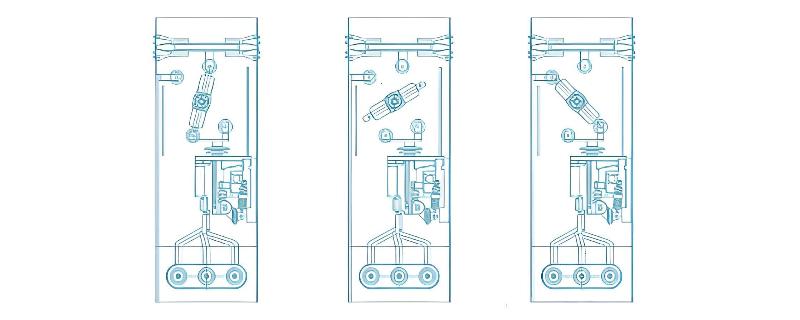
Owing to the low dielectric strength of dry air, solid insulation cannot solve the problem of voltage withstand at the isolation break. A double-break disconnector uses two gas gaps in series to effectively divide the voltage. Electric field shielding and grading rings are designed at locations with concentrated electric fields, such as the stationary contacts of the isolator and grounding switch, to reduce electric field intensity and effectively minimize the size of the air gap. As shown in Figure 1, the double-break mechanism achieves operational states—working, isolated, and grounded—through enhanced rotation of a nylon main shaft. The grading ring at the stationary contact has a diameter of 60 mm and is treated with epoxy vulcanization; a 100 mm clearance can withstand a 150 kV lightning impulse voltage.

Other solutions, such as longitudinal single-phase arrangement using high-strength alloy enclosures for each phase or moderately increasing the gas pressure, can also meet the 24 kV dielectric requirements. However, ring main units (RMUs) require low cost, and excessively high costs are unacceptable to users. Through optimized design and moderate widening of the RMU cabinet, it is possible to achieve low-cost and compact 24 kV environmentally friendly gas-insulated RMUs.
Arrangement of Grounding Switch in Eco-Friendly Gas RMUs
There are two methods in RMUs to achieve grounding function in the main circuit:
Outgoing line-side earthing switch (lower earthing switch)
Busbar-side earthing switch (upper earthing switch)
The busbar-side earthing switch can be selected as Class E0, which requires coordination with the main switch during operation. According to the Standardized Design Scheme for 12 kV Ring Main Units (Boxes) issued by State Grid in 2022, regarding three-position switches, the scheme specifies that three-position switches should adopt a busbar-side arrangement and redefines them as "busbar-side combined functional earthing switches."
Power safety regulations stipulate that no circuit breaker or fuse shall be connected between grounding wires, earthing switches, and equipment under maintenance. If, due to equipment constraints, a circuit breaker exists between the earthing switch and the equipment under maintenance, measures must be taken to ensure that the circuit breaker cannot open after both the earthing switch and the circuit breaker have been closed.
Therefore, the line-side earthing switch is located downstream of the circuit breaker. It connects directly to the outgoing cable being grounded, satisfying the requirement that no circuit breaker or fuse exists between the grounding point, the earthing switch, and the equipment under maintenance. In contrast, the busbar-side earthing switch is located upstream of the circuit breaker. There is a vacuum circuit breaker between the earthing switch and the outgoing cable being grounded—it does not connect directly. Since a circuit breaker lies between the earthing switch and the equipment under maintenance, measures must be implemented to prevent the circuit breaker from opening once both the earthing switch and the circuit breaker are closed. For example, the trip circuit of the circuit breaker may be disconnected via a link plate, or mechanical means may be used to prevent accidental tripping, thereby avoiding unintended disconnection of the grounding path.
The State Grid Standardized Design Scheme also specifies interlocking requirements for the busbar-side combined functional earthing switch. When the combined functional earthing switch on the busbar side uses closure of the circuit breaker to achieve grounding of the cable side, it must include both mechanical and electrical interlocks to prevent manual or electric opening of the circuit breaker.

State Grid adopts the busbar-side three-position isolation/grounding switch primarily considering the short-circuit making (closing) capability. In SF6-insulated RMUs, the earthing switch benefits from SF6’s dielectric strength being about three times that of air and its arc-quenching capability approximately 100 times greater than air due to superior arc cooling. Thus, the closing capacity of the earthing switch is reliably ensured.
In contrast, eco-friendly gases lack arc-quenching capability and have lower insulation performance. Therefore, very high closing speed is required. However, RMU operating mechanisms have limited energy and cannot provide sufficient force for high-speed closing. Using a line-side earthing switch would require increased closing speed and improved arc resistance and electrodynamic analysis of the contacts, potentially leading to larger operating forces and higher costs. The busbar-side earthing switch, by solving the circuit breaker interlock issue, can still ensure reliable grounding while offering stronger making capacity.
Through technical and product analysis of SF6 versus eco-friendly gases, it can be seen that 12 kV eco-friendly gas-insulated RMUs can meet insulation and temperature rise requirements with only minor increases in size, indicating mature technical solutions.
However, there are few 24 kV eco-friendly gas-insulated products available. The key challenge lies in the higher voltage rating, which leads to significantly increased dimensions. Excessive size and high price will restrict the development of 24 kV eco-friendly gas-insulated RMUs. A balanced approach considering insulating gas type, filling pressure, enclosure volume, and auxiliary insulation cost is needed to design low-cost, compact RMUs. Only then can true SF6 replacement be achieved—enabling not only domestic market dominance but also global export, promoting China's low-carbon, environmentally friendly electrical equipment worldwide.