What is an Auto Transformer?

What is an Auto Transformer?
Auto Transformer Definition
An auto transformer is defined as a type of electrical transformer with a single winding acting as both the primary and secondary winding.
Single Winding Theory
An auto transformer uses a single winding for both the primary and secondary purposes, unlike two-winding transformers which use separate windings. The diagram below illustrates this concept.

The winding AB of total turns N1 is considered as primary winding. This winding is tapped from point ′C′ and the portion BC is considered as secondary. Let’s assume the number of turns in between points ′B′ and ′C′ is N2.
If V1 voltage is applied across the winding i.e. in between ′A′ and ′C′.
Hence, the voltage across the portion BC of the winding, will be,
As BC portion of the winding is considered as secondary, it can easily be understood that value of constant ′k′ is nothing but turns ratio or voltage ratio of that auto transformer. When load is connected between secondary terminals i.e.between ′B′ and ′C′, load current I2 starts flowing. The current in the secondary winding or common winding is the difference of I2 and I1.

Copper Savings
Auto transformers save copper because they use less winding material, making them more efficient and cost-effective.
Auto Transformer Advantage
Thus auto transformer is smaller in size and cheaper.
An auto transformer has higher efficiency than two winding transformer.
Auto transformer has better voltage regulation as voltage drop in resistance and reactance of the single winding is less.
Auto Transformer Disadvantage
Due to the electrical conductivity between the primary and secondary windings, the lower voltage circuit may be affected by the higher voltage. To prevent breakdown, the low voltage circuit must be designed to withstand the higher voltage.
The impedance is low. This results into severer short circuit currents under fault conditions.
This introduces complications due to changing primary and secondary phase angle particularly in the case of delta/delta connection.
Maintaining the electromagnetic balance of the winding is harder when voltage adjustment tappings are used. Adding tappings increases the transformer frame size, and if the tapping range is large, the initial cost savings are significantly reduced.
Applications of Auto Transformers
Compensating voltage drops by boosting supply voltage in distribution systems.
Auto transformers with a number of tapping are used for starting induction and synchronous motors.
Auto transformer is used as variac in laboratory or where continuous variable over broad ranges are required.


-
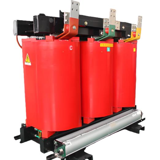
35kV Three-phase Epoxy Cast Dry Distribution Transformer

-
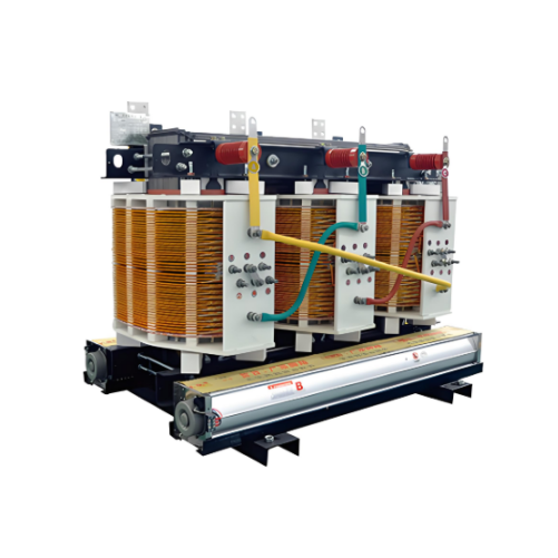
Resin-insulated Dry Type Transformer 800kVA 1000kVA 1250kVA 1600kVA 2000kVA 2500kVA
-
Dry type power transformers 500kVA 1000kVA,35kV dry type distribution transformer,800 kVA dry transformer 3 phase

-
Non-encapsulated H-class Dry-type Power Transformers 800kVA 1000kVA 1250kVA 1600kVA 2000kVA 2500kVA