Equivalent Circuit of a Transformer

06/03/2025

The equivalent circuit diagram of any device can be extremely useful for predicting how the device will behave under different operating conditions. It is essentially a circuit - based depiction of the equations that describe the device's performance.
The simplified equivalent circuit of a transformer is constructed by representing all of the transformer's parameters on either the secondary side or the primary side. The equivalent circuit diagram of the transformer is presented below:

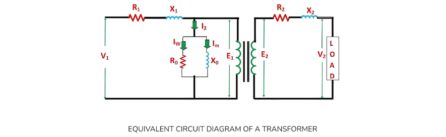
Let the equivalent circuit of a transformer be considered, with a transformation ratio K = E2/E1.The induced electromotive force E1 is equivalent to the primary applied voltage V1 minus the primary voltage drop. This voltage gives rise to the no - load current I0 in the primary winding of the transformer. Since the value of the no - load current is extremely small, it is often neglected in many analyses.Consequently,  I1I1. The no - load current I0 can be further decomposed into two components: the magnetizing current Im and the working current Iw.These two components of the no - load current are a result of the current drawn by a non - inductive resistance R0 and a pure reactance X0, across which the voltage is E1 (or equivalently, V1primary voltage drop).

The terminal voltage V2 across the load is equal to the induced electromotive force E2 in the secondary winding minus the voltage drop in the secondary winding.
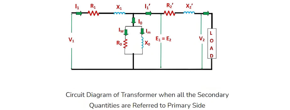
Equivalent Circuit with All Quantities Referred to the Primary Side
In this scenario, to construct the equivalent circuit of the transformer, all parameters need to be referred to the primary side, as depicted in the figure below:

The following are the values of resistance and reactance given below

Secondary resistance referred to the primary side is given as:

The equivalent resistance referred to the primary side is given as:

Secondary reactance referred to the primary side is given as:

The equivalent reactance referred to the primary side is given as:

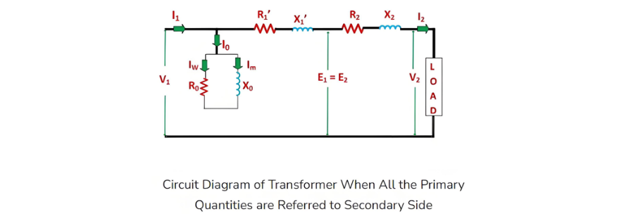
Equivalent Circuit with All Quantities Referred to the Secondary Side
The following is the equivalent circuit diagram of the transformer when all parameters are referred to the secondary side.

The following are the values of resistance and reactance given below

Primary resistance referred to the secondary side is given as

The equivalent resistance referred to the secondary side is given as

Primary reactance referred to the secondary side is given as

The equivalent reactance referred to the secondary side is given as

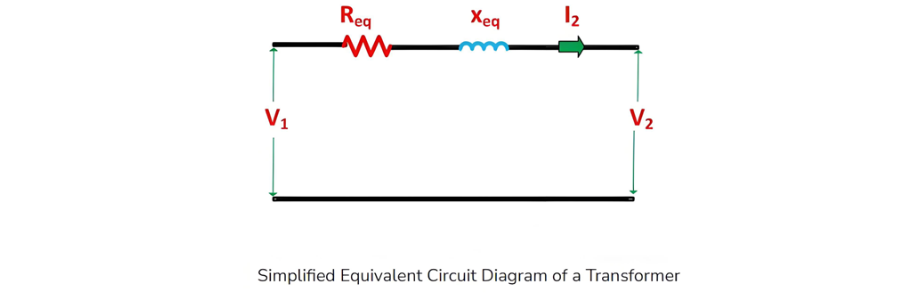
Simplified Equivalent Circuit of Transformer
Since the no-load current I0 typically accounts for only 3 to 5% of the full-load rated current, the parallel branch comprising resistance R0 and reactance X0 can be omitted without introducing significant errors in analyzing the transformer's behavior under loaded conditions.
Further simplification of the transformer's equivalent circuit is achieved by neglecting this parallel R0-X0 branch. The simplified circuit diagram of the transformer is as follows:

Wenzhou Rockwell Transformer Co., Ltd. It is a high - tech enterprise integrating R & D, production, sales, and service. It focuses on the manufacturing of power transformers and supporting equipment, and is committed to providing efficient, reliable, and energy - saving power transmission and distribution solutions for global customers. We can offer: •Distribution transformers and substations •Outdoor switchgears and breakers(recloser) •Switchgears and it’s components (GIS, RMU, VCB, SF6 CB) Market and Service: We always take customers as the orientation and provide customized services according to their requirements. Our products are exported to the Middle East, Africa, Northern Europe, South America, and many other countries and regions. Drive the future of electricity with technological innovation and become a leading global supplier of intelligent power equipment.

Fault Analysis and Treatment of Oil-Immersed Transformers
Oil Leakage at Welded JointsOil leakage at welded joints primarily stems from poor welding quality, such as incomplete or detached welds, and defects like pinholes and gas pores. Although oil-immersed transformers are initially coated with solder and paint during manufacturing, potentially masking these issues temporarily, the defects tend to surface during operation. Additionally, electromagnetic vibration can cause weld cracks, leading to oil leakage.To resolve such leaks, the first critical s
08/29/2025
What losses occur during operation of the transformer? How to reduce losses?
Transformers experience various types of losses during operation, primarily categorized into two main types: copper losses and iron losses.Copper LossesCopper losses, also known as I²R losses, are caused by the electrical resistance of the transformer windings—typically made of copper. As current flows through the windings, energy is dissipated in the form of heat. These losses are proportional to the square of the load current (I²R), meaning they increase significantly with high
Rockwell
08/29/2025
Transformer Detection, Testing, Maintenance and Servicing
Transformer testing, inspection, and maintenance are essential tasks to ensure normal operation and extend the service life of transformers. Below are some recommended steps:Visual Inspection: Regularly inspect the transformer's exterior, including the enclosure, cooling system, and oil tank. Ensure the enclosure is intact, free from corrosion, damage, or leakage.Insulation Resistance Testing: Use an insulation resistance tester to check the transformer's insulation system. Verify that the insul
Vziman
08/29/2025
Preventive Detection and Testing of Transformers
I. DC Resistance Test of Transformer Primary and Secondary Windings:The DC resistance of transformer primary and secondary windings can be measured using the four-wire (Kelvin) method, which is based on principles related to accurate resistance measurement.In the four-wire method, two test leads are connected to both ends of the winding under test, while the other two leads are connected to adjacent winding terminals. An AC power source is then applied to the two leads connected to the adjacent
Rockwell
08/28/2025
Inquiry
Download
IEE-Business is dedicated to serving the personnel in the global power industry.
Join IEE-Business, not only can you discover power equipment and power knowledge, but also canhnd like - minded friends!