What are the common faults and handling methods of the operating mechanisms of 35kV and 10kV indoor vacuum circuit breakers?

In power system operation and maintenance, we have found that 35kV and 10kV indoor vacuum circuit breakers, as core primary equipment of high-voltage switchgear, are widely used in main grid and user substations due to their high reliability and low maintenance workload. From daily inspections and live detection to routine maintenance, vacuum circuit breakers always remain our key focus, as their operational quality is directly related to the stability and reliability of the power system. This paper focuses on the action principles of their spring operating mechanisms, analyzes prominent issues in our operation and maintenance practices, and proposes targeted treatment measures.
Introduction to Operating Mechanisms of Indoor Vacuum Circuit Breakers
As we know, indoor vacuum circuit breakers mainly consist of spring operating mechanisms, arc extinguishing mechanisms, conductive contacts, support insulators, and outlet terminals (as shown in Figure 1). The spring operating mechanism, a key component for us, is composed of an energy storage device, opening-closing device, operation panel, and control circuit. We drive the circuit breaker to open or close through the spring operating mechanism by remotely or locally operating the opening/closing buttons, achieving on-off control of the power system.
Brief Introduction to Energy Storage Mechanism
As shown in Figure 2, the energy storage device of the spring operating mechanism for vacuum circuit breakers we maintain features a cast aluminum housing reduction gearbox with two sets of worm gears inside. The energy storage shaft runs through the reduction gearbox, with a bearing connected to the large worm gear by a key sleeved on the shaft and a pawl mounted on the bearing. The right end of the energy storage shaft is equipped with a notched cam, through which the pawl drives the cam to rotate; the left end is fitted with a crank, where one end of the closing spring is hung.
A triangular lever with a needle bearing is mounted on the pin of the reduction gearbox. When releasing closing energy, we observe that the cam transmits the closing spring's energy to the needle bearing. The lever connects to a connecting rod through a pin, whose other end links to the main shaft crank arm, forming a four-bar mechanism to transmit closing force to the switch main shaft. Additionally, a small roller bearing on the reduction gearbox pin locks the closing latch to maintain the closing spring's energy.
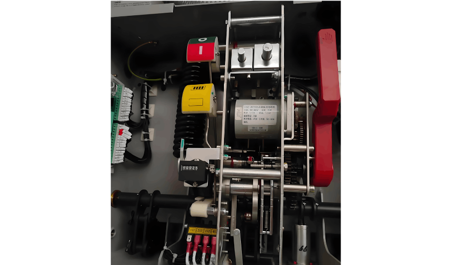
Principle of Electric Energy Storage
When we close the motor power supply during operation, the shaft sleeve of the energy storage shaft is driven by the large worm gear in the reduction gearbox to rotate. The pawl on the shaft sleeve quickly embeds into the cam's notch, driving the energy storage shaft to rotate and gradually stretch the closing spring for energy storage. When the spring is stretched to its highest point, the small connecting rod on the crank drives the bending plate to press the microswitch, cutting off the motor power. Meanwhile, the closing spring is locked by the closing latch, with the entire energy storage process taking less than 15 seconds.
Principle of Closing Action
Currently, the 35kV and 10kV vacuum circuit breakers we maintain mostly adopt spring operating mechanisms, which store energy by rotating the energy storage motor to stretch the energy storage spring to a set length. When we activate the closing coil or press the closing button by hand, the closing latch is unlocked, and the energy storage shaft rotates counterclockwise under the closing spring's force. The cam presses the needle bearing on the triangular lever, which transmits force to the switch main shaft through the connecting rod. The main shaft drives the insulating pull rod and moving conductive rod upward. After rotating to a specific angle, the main shaft is locked by the opening latch to complete closing, while the opening spring is energized.
"Failure to Close" Fault
During operation and maintenance, we have found that when closing remotely, the closing coil thimble acts but the impact force is insufficient to disengage the roller from the closing holding latch, causing the spring energy to fail to release - the "failure to close" phenomenon. The coil often overheats or burns out due to prolonged energization. Another case is misoperation of the rotary handle to the "sectionalization lock" position, which mechanically locks the circuit breaker and leads to coil burnout.
On - site inspection shows tight contact and high friction between the latch and roller, making manual closing difficult. Dry oil residue on the roller increases resistance. Our solution: power off, release spring energy, lubricate the latch and roller with machine oil, scrape off residue, and perform multiple operations for verification. Replace the coil if burned.
"Failure to Open" Fault
The "failure to open" fault shares similar principles and manifestations with "failure to close". However, during power outage operations, it prevents opening, and a burned opening coil requires on - site manual operation.
Energy Storage Fault
After each closing, the energy storage motor automatically resets the spring. A microswitch cuts off the circuit when storage is complete. The storage circuit consists of an air switch, motor, and normally closed microswitch contacts. For failure to store energy, we first check the air switch and voltage, then the microswitch. Long - unused breakers often have stuck microswitches; motor faults or poor connections are less common, with microswitch failure being the main cause.
Conclusion
The three faults analyzed are typical in operating mechanisms. Regular inspection and maintenance are essential to reduce failures and ensure power supply reliability.


