
Ang mga fuse gitugyan sa serye sa isang circuit. Kung ang kuryente nga nagaagad sa fuse element adunay kauban o parehas sa iyang rated current, ang elemento wala mosunog. Lamang kung ang kuryente moadto sa dako pa sa rated value ug maabot sa fusing current ang elemento mosunog. Kung may short circuit (o overload) na kuryente sa linya, ang kuryente nga nagaagad sa fuse element moadto sa dako pa sa gipangutana, kasagaran nagresulta sa pag-overheat ug pag-sunog sa elemento, resulta niini ang circuit automatic nga mag-interrupt. Kini makapahimulos sa power grid o electrical equipment ug makapahimulos sa mga aksidente, samtang protektahan ang mga electrical devices sa circuit. Sa 3kV–35kV small-capacity installations, ang mga fuse mahimong gamiton aron maprotektahan ang lines, transformers, motors, ug voltage transformers.
Sumala, atong ipasabot ang mga structural features, selection, ug pipila ka teknikal nga detalye sa installation para sa 10kV pole-mounted expulsion-type fuses.
1. Structure and Features of Common 10kV Pole-Mounted Expulsion-Type Fuses
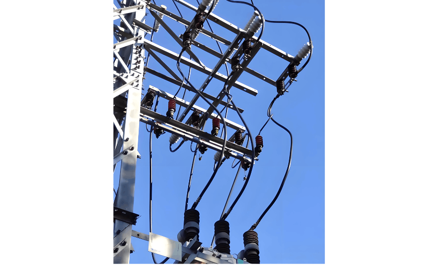
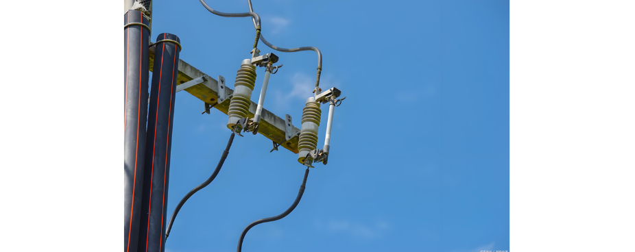
Ang RW10–10F ug RW11–10 duha ka commonly used types of general-purpose expulsion-type fuses, giilustrar sa Figures 1 ug 2. Kada modelo adunay iyang kaugalingon nga characteristics. Ang una gamiton ang spring force sa coil spring aron mapresyon ang contacts tightly, may arc extinguishing chamber ug arcing contacts gisulod sa upper end, makahimo og live-line operation for opening ug closing. Ang uban gamit ang spring force aron mapresyon ang contacts pero dili mahimo og operate under load. Ang fuse tubes ug upper/lower contact conductive systems sa duha ka models adunay slightly different structural dimensions. Aron masiguro ang interchangeability sa fuse tubes ug fuse wires samtang imo gi-handle ang fault ug pangutana ang number sa spare parts, advisable ang paggamit lamang og usa ra ka model sa expulsion-type fuse sa usa ka maintenance area.
Sa normal nga operasyon, ang fuse wire maandam nga gitighten pinaagi sa tensioning device, securing ang movable joint sa fuse tube ug keeping ang tube sa closed position. Kung ang overcurrent magresulta sa pag-sunog sa fuse wire, ang arc generated sa break inside sa fuse tube. Ang arc extinguishing tube lining mogenerate og large amount sa high-pressure gas pinaagi sa action sa arc, promoting rapid arc extinction. Subsequently, ang spring bracket quick nga ejects ang fuse wire gikan sa tube, samantalang ang fuse tube rapid nga drops open pinaagi sa combined force sa upper ug lower elastic contacts ug iyang kaugalingon nga weight, creating a clear isolation gap ug completing the circuit interruption.
Sa upper end sa fuse tube, adunay pressure-release cap nga naglaman og low-melting-point fuse plate. Kung interrupting high currents, ang thin fuse plate sa upper cap mosunog, resulting in dual-end gas exhaust. Kung interrupting low currents, ang thin fuse plate intact, resulting in single-end gas exhaust.
2. Selection Principles for Expulsion-Type Fuses
1) Selection of Fuse Specifications:
Rated Voltage: Pili og voltage equal or higher sa grid's rated voltage. Para sa 10kV distribution network, pili og 10kV expulsion-type fuse, sama sa RW10–10F o RW11–10.
Rated Current: Ang fuse's rated current dapat greater than or equal sa rated current sa fuse element.
2) Selection of Fuse Element Rated Current:
Para sa distribution transformers above 100kVA, ang rated current sa high-voltage side fuse wire selected at 1.5 to 2 times ang transformer's high-voltage side rated current.
Para sa distribution transformers of 100kVA and below, ang rated current sa high-voltage side fuse wire selected at 2 to 3 times ang transformer's high-voltage side rated current.
Ang rated current sa low-voltage side fuse wire para sa distribution transformers selected at 1 to 1.2 times ang transformer's low-voltage side rated current.
3. Hazard Control and Safety Precautions During Installation
1) Hazard Control:
Risk of falling from height o being struck by falling objects.
Before climbing the pole, check that the pole base, climbing tools, ug foot spikes secure.
Workers must wear safety harnesses ug safety helmets. The safety harness should be attached to the pole o a sturdy component, avoiding sharp objects that could cause cuts.
Materials, tool bags, ug tools should be passed using ropes. Workers on the pole must prevent dropping items, ug a barrier should be set up on the ground.
Prevent slipping when using foot grips to climb the pole.
Use an appropriate wrench to prevent slippage ug injury.
Before work, emphasize the names of adjacent energized equipment ug the specific line, starting ug ending pole numbers.
Clearly communicate information about adjacent, crossing, overpassing, o parallel energized lines ug assign a dedicated supervisor.
Pole climbing inspections must be performed by two people: one working ug one supervising. Before climbing, confirm the de-energized line name ug pole number. The supervisor may only participate in work when the worker is safe, but the worker must remain within the supervisor's line of sight.
For pole climbing inspections, all low-voltage lines ug street light lines that are crossed must be verified as de-energized ug equipped with temporary grounding wires.
2) Safety Precautions:
Power-off installation work should be conducted in good weather. Do not work during thunderstorms, rain, snow, o high winds.
After installation, perform open/close tests on the fuse tube to ensure good contact.
Copper-aluminum connections should use copper-aluminum transition measures.
Check that the selected fuse wire matches the capacity of the protected equipment.
It is strictly prohibited to use copper or aluminum wire as a substitute for high-voltage fuse wire.
4. Preparations Before Installation
1) Personnel Organization:
1 work supervisor, 1–2 line workers.
2) Required Tools, Equipment, and Materials:
Hoisting rope.
Expulsion-type fuse.
Crossarm for the expulsion-type fuse.
Conductors.
Copper-aluminum terminal connectors.
Copper stranded wire (or aluminum stranded wire).
3) Pre-Installation Checks:
Verify that the fuse specifications and model are appropriate, with a manufacturer's name and factory certificate of conformity.
Check that all fuse components are complete and undamaged, with no cracks or damage on the porcelain parts.
Ensure the shaft is smooth and flexible, with no cracks, sand holes, or rust on cast parts.
The fuse tube should show no signs of moisture absorption, swelling, or bending.
Check that the static and dynamic contacts have good contact and that the contact spring elasticity is appropriate.
5. Installation Procedure
Verify that the specifications and model of the expulsion-type fuse match the design, and that documentation is complete.
Assemble and adjust the expulsion-type fuse, fuse tube, and upper/lower leads. Use equipment clamps to connect the leads to the fuse.
Install the crossarm and other fittings; install the crossarm in the designated position according to design requirements.
Install the expulsion-type fuse:
During installation, tighten the fuse element to prevent overheating at the contacts.
The fuse must be securely and reliably mounted on the crossarm (structure), with no shaking or wobbling.
The angle between the axis of the fuse tube and the vertical ground should be 15°–30° to allow the tube to drop quickly under its own weight when the element melts.
The fuse should be installed on a crossarm (structure) at a vertical height of no less than 4.7m from the ground. If installed above a distribution transformer, maintain a horizontal distance of more than 0.5m from the outermost boundary of the transformer to prevent secondary accidents if the tube falls.
The length of the fuse tube should be properly adjusted. After closing, the duckbill tongue should engage more than 2/3 of the contact length to prevent unintended dropping during operation. The tube should not be jammed in the duckbill to ensure it can drop promptly after the element melts.
10kV expulsion-type fuses are installed outdoors, requiring a phase-to-phase distance greater than 0.5m.
(5) Connect the upper and lower leads of the expulsion-type fuse; the connections to the line conductors must be tight and reliable.
6. Installation Craftsmanship Requirements
The upper and lower leads of the expulsion-type fuse must be reliably connected with good contact.
When connecting copper to aluminum, use copper-aluminum transition clamps.
After installation, the RW-type fuse tube should form an angle of approximately 30° with the pole.
The fuse tube should be clean, crack-free, undeformed, and free of welding marks. The indicator should be intact and pointing downward. The resistance value of the fuse tube should meet the manufacturer's standards, or the difference between the three-phase resistance values should be less than 20%.
The contact seat should be clean, free of rust or burn marks. If uneven, use a fine file to level it and sandpaper to polish it. Replace if the required condition cannot be achieved after treatment.
Clean the base of the connection plate, polish with sandpaper, wipe clean, apply electrical grease or neutral petroleum jelly, and tighten the bolts.


