The substation automation system (SAS), as its name implies, is distinguished by its capacity to substitute automated functions for manual operator tasks. Automated operations play a crucial role in guaranteeing the safe and reliable operation of electric power transmission and distribution. Its functions include, but are not limited to, monitoring, data collection, protection, control, and remote communication.
Previously, Remote Terminal Units (RTUs) were solely employed as intermediaries between the electric power switchgear at the process level in substations and the network management system of utilities for long - range surveillance purposes (refer to Figure 1 below).
These units are furnished with multiple inputs and outputs, serving as communication interfaces to remote network control centers. The Remote Terminal Units (RTUs) and the Network Control Center (NCC) together constitute the Supervisory Control and Data Acquisition System (SCADA), as depicted in Figure 1.
There are several notable specific functions of the substation automation system:
For example, many functions in the Substation Automation System (SAS) are coordinated to automatically restore from equipment malfunctions or short - circuit failures. These functions involve multiple devices, with their responsibilities allocated between primary equipment (such as circuit breakers, transformers, instrument transformers, etc.) and secondary equipment (such as protective relays, merging units, intelligent electronic devices).
Figure 1 - The Substation Automation System: Architecture of Classical SCADA Systems
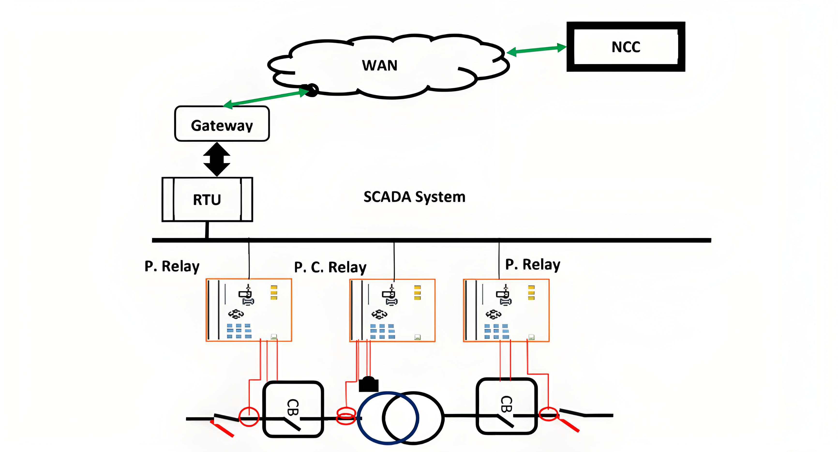
Consequently, the cabling and wire connections among these devices and equipment become complex, necessitating substantial effort and extended time for maintenance, repair, expansion, or modification operations. Efforts have been made to reduce the amount of cabling and wiring by implementing serial communication networks at different levels of the substation hierarchy. These initiatives have led to proprietary solutions developed by substation equipment providers.
Major corporations, including non - profit groups such as the Utility Communication Architecture (UCA) which is composed of substation equipment suppliers and utility users, are actively working on improving substation communications. They are doing so by participating in the development of international standards to enhance functional compatibility and proposing architectures that offer higher network bandwidth.The goal is to improve the reliability of communication both within substations and between different substations.
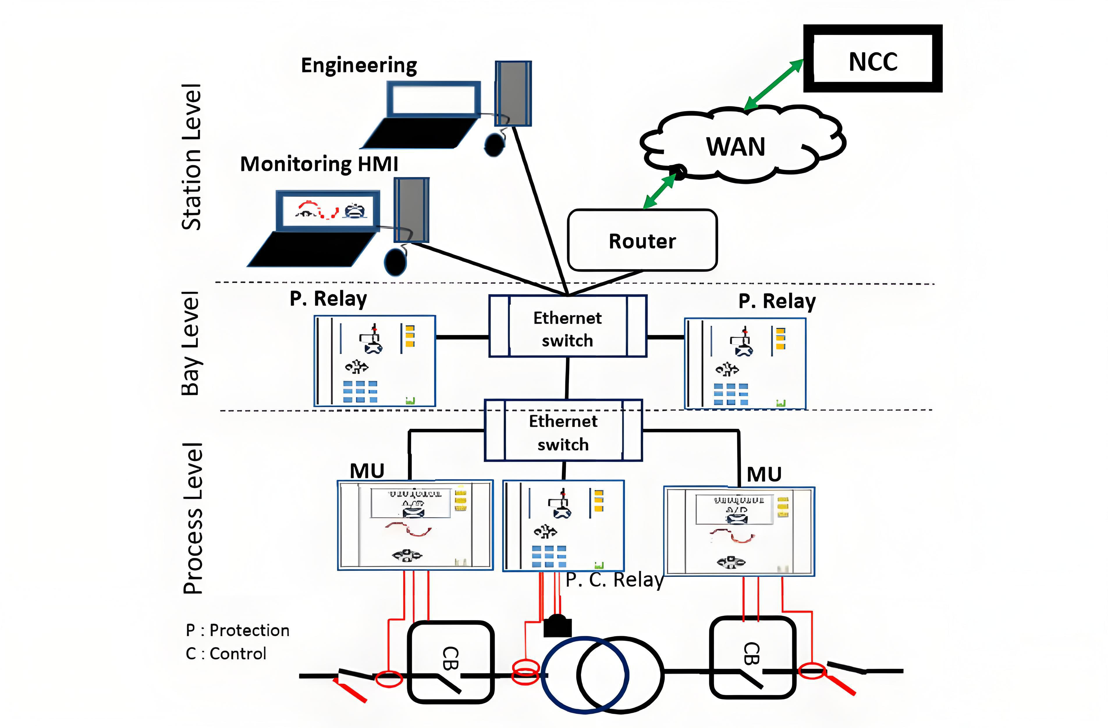
The substation automation hierarchical architecture in SAS is categorized based on technological implementations. The substation automation system comprises three levels: the station level, the bay level, and the process level (as illustrated in Figure 2). These levels can be harnessed to achieve diverse functionality. In terms of technical specifications, the dimensions of a substation automation system (SAS) in extra high voltage transmission substations will be larger compared to those in high voltage distribution substations.
In modern substations, the bay level is a common feature, though during the early days of SAS, the concept of the bay level was not recognized.
Typically, sensors measure extremely large current and voltage magnitudes. Current and voltage transformers (CTs/VTs) are employed to convert substantial amounts of current and voltage into standardized values, which are then fed into relay inputs. The scaled values usually correspond to 5A (1A in Europe) for current and 120 Volts for voltage.In essence, protective relays or modern intelligent electronic devices implement the protective logic.
Figure 2 - The structure of a Substation Automation System depicting station, bay, and process levels
These devices detect and measure electrical current and voltage levels to calculate certain values that are monitored by the protective logic, such as the electrical current on the two different sides of an Extra High Voltage (EHV)/High Voltage (HV) transformer. When a parameter exceeds a specified value (pickup setting), the protective logic will act according to a predefined sequence of steps or a programmed control algorithm.Typically, when an issue arises, a trip signal is sent to the corresponding circuit breaker to isolate a line or bus.