What Essential Tests Must Qualified Combined Instrument Transformers Undergo?

Hi everyone, I’m Oliver, and I’ve been working in the instrument transformer industry for almost eight years now. From a complete newbie to someone who can now handle things independently, I’ve participated in dozens of combined instrument transformer inspections over the years.
Today, I’d like to share with you: What tests must a qualified combined instrument transformer go through before leaving the factory or being put into operation? After all, it's a very critical piece of equipment in the power system — there’s no room for carelessness.
1. Insulation Test: Is the “Protective Layer” Reliable?
First and most importantly, we have the insulation performance test. Combined instrument transformers usually operate at high voltages like 35kV. If the insulation isn’t up to standard, it could cause anything from inaccurate measurements to short circuits or even explosions.
We perform several key tests:
Insulation resistance test – using a megohmmeter to measure the insulation resistance between windings, which should generally be no less than 1000MΩ.
Power frequency withstand voltage test – simulating extreme voltage conditions to see if the transformer can withstand voltage surges higher than its rated level for a short time.
Partial discharge test – to detect any tiny internal defects like bubbles or cracks, which could lead to major issues during long-term operation.
I once dealt with a customer complaint where the transformer broke down after just a few months of operation. The root cause was poor insulation treatment. So this step really cannot be skipped!
2. Ratio and Error Test: Accuracy Is the Key!
One of the core functions of a combined instrument transformer is to accurately measure current and voltage, which means its ratio must be precise, and the error must be within standard limits.
We usually perform:
Ratio test – verifying that the voltage and current ratio between the primary and secondary sides matches the design specifications.
Error test (ratio error and phase error) – especially for metering-grade transformers, the error must be controlled within ±0.2%.
Sometimes, customers say things like, “My transformer looks fine, but the electricity bills never match.” That’s when we usually suspect the error has exceeded acceptable limits. So this step directly affects the user’s interests.

3. Polarity Test: If the Direction Is Wrong, Everything Goes Wrong!
Don’t underestimate this step — the polarity test is really important. If the polarity of the transformer is reversed, it can cause the protective relay to misjudge and even disable the entire protection system.
We use either the DC method or AC method to confirm the polarity of the transformer. Especially for combined transformers, which contain both voltage and current components, the polarity must match exactly — otherwise, the whole system could fail.
4. Volt-Ampere Characteristic Test: The “Ultimate Challenge” for Current Transformers
This test mainly applies to the current transformer part. The volt-ampere characteristic reflects the magnetization performance of the iron core and helps us determine whether the transformer can function properly under fault current without saturation.
We gradually increase the voltage, record the current changes, and draw the volt-ampere curve. If the curve is abnormal, it indicates there may be a problem with the core, and the unit needs to be sent back for repair.
I remember a project where the customer reported that the protection system kept malfunctioning. After checking the volt-ampere curve, we found the core was already severely saturated — that was the root of the problem.
5. Short Circuit and Open Circuit Test: Simulating Extreme Conditions
To verify the transformer’s performance under abnormal conditions, we also perform:
Secondary short circuit test – checking the protection performance of the voltage transformer when the secondary side is shorted.
Secondary open circuit test – observing whether the current transformer generates overvoltage when open-circuited.
These tests aren’t part of the regular routine, but they are essential for special applications, such as important substations or new energy grid-connection projects.
6. Temperature Rise Test: Can It Handle the Heat?
During long-term operation, instrument transformers will generate heat. If the heat dissipation design is poor or the materials can’t withstand high temperatures, it could lead to insulation aging or even burnout.
We simulate rated or even overloaded conditions and measure the temperature rise across different parts to ensure it stays within acceptable limits.
This test is especially important in high-temperature environments or areas with high load demands.
7. Sealing Test (for SF6 Transformers)
For SF6 gas-insulated combined instrument transformers, the sealing test is a must. If the gas leaks, it not only affects insulation performance but also causes environmental pollution and can even endanger personal safety.
We use infrared imaging leak detectors or gas leak detectors to thoroughly inspect all sealing surfaces and weld points.
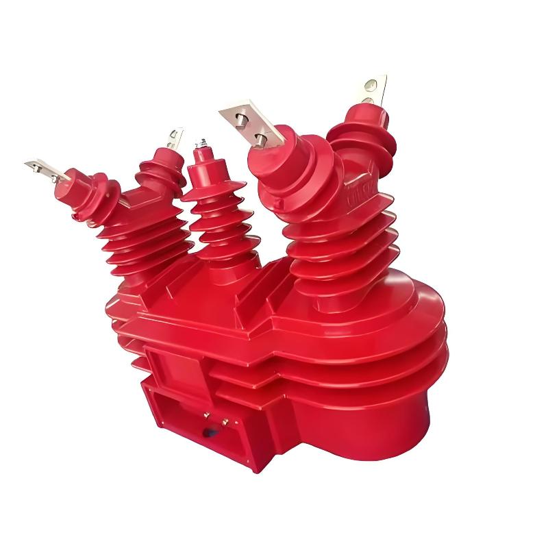
8. Appearance and Structure Inspection: Details Make the Difference
Don’t think this is just superficial — the appearance and structure inspection is actually very important. We check:
Whether the housing is deformed or cracked
Whether the terminal connections are tight and clearly marked
Whether the nameplate information is accurate
Whether the installation structure is reasonable
Once, we found a loose grounding terminal on a transformer. While it might seem minor, if it goes unnoticed and is put into operation, the consequences could be serious.

Conclusion: Being Qualified Is Not the Goal — Safety Is the Foundation
As someone who has worked in the instrument transformer industry for eight years, I know firsthand that behind every qualified combined instrument transformer are layers of strict testing. Each test isn’t just a formality — it ensures that the equipment can operate stably, safely, and reliably in real-world conditions.
If you're in the industry, I hope this article helps you organize the testing process. And if you're a client or engineer, I hope it gives you a better understanding of what goes on behind the scenes with instrument transformers.
A qualified instrument transformer isn’t just about words — it’s truly “tested” into existence.
I’m Oliver — catch you next time for more instrument transformer insights. Bye!