• Product
  • Suppliers
  • Manufacturers
  • Solutions
  • Free tools
  • Knowledges
  • Experts
  • Communities
Search


What Are Combined Transformer Standards? Key Specs & Tests

Edwiin
Edwiin
Field: Power switch
China

Combined Instrument Transformers: Technical Requirements and Testing Standards Explained with Data

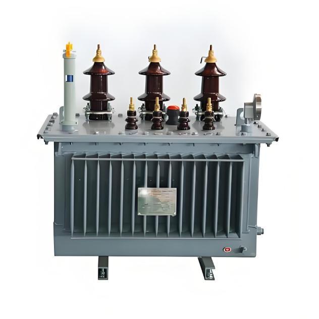
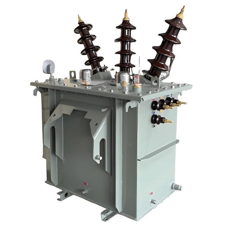
A combined instrument transformer integrates a voltage transformer (VT) and a current transformer (CT) into a single unit. Its design and performance are governed by comprehensive standards covering technical specifications, testing procedures, and operational reliability.

1. Technical Requirements

Rated Voltage:
The primary rated voltages include 3kV, 6kV, 10kV, and 35kV, among others. The secondary voltage is typically standardized at 100V or 100/√3 V. For example, in a 10kV system, the primary rated voltage of the combined transformer is 10kV, while the secondary output is 100V—meeting both measurement and protection requirements.

Rated Current Ratio:
The CT section offers various rated current ratios such as 50/5, 100/5, and 200/5. These ratios can be selected based on actual system current levels to accurately transform primary current to the secondary side (typically 5A), ensuring precise monitoring and relay protection operation.

2. Testing Standards

Insulation Tests:
These verify the dielectric strength of the transformer under normal and transient overvoltage conditions.

  • Power Frequency Withstand Test:
    For a 10kV combined transformer, the test voltage is typically 42kV RMS, applied for 1 minute. This ensures the insulation can withstand sustained power-frequency overvoltages during service.

  • Impulse Withstand Test:
    The peak impulse voltage is generally 75kV, simulating lightning surge conditions. This test evaluates the transformer’s ability to endure transient overvoltages without breakdown.

Accuracy (Error) Tests:
Strict error limits are defined based on accuracy classes.

CT VT.jpg

  • Voltage Transformer (0.2 Class):
    At rated voltage, the ratio error must not exceed ±0.2%, and the phase angle error must be within ±10 minutes (′).

  • Current Transformer (0.2S Class):
    Over a wide range from 1% to 120% of rated current, the ratio error remains within approximately ±0.2%, with tightly controlled phase angle error. This high accuracy is essential for metering applications, especially under low-load conditions.

Temperature Rise Test:
This test ensures safe long-term operation under full load.

  • Conducted at rated load and specified ambient temperature (usually 40°C), the average winding temperature rise must not exceed 65K. This limit prevents insulation degradation and ensures reliable performance over the transformer’s service life.

Summary

Combined instrument transformers are engineered to meet rigorous international standards (such as IEC 61869 series and GB/T 20840). Their technical parameters—like 10kV primary voltage, 100V secondary output, and 100/5 current ratio—are selected based on system requirements. Compliance with tests including 42kV power frequency, 75kV impulse withstand, ±0.2% accuracy, and 65K temperature rise guarantees safety, precision, and durability in power systems.

Give a tip and encourage the author!
Recommended
How does the oil in oil-immersed power transformers clean itself?
The self-cleaning mechanism of transformer oil is typically achieved through the following methods: Oil Purifier FiltrationOil purifiers are common purification devices in transformers, filled with adsorbents such as silica gel or activated alumina. During transformer operation, convection caused by oil temperature changes drives the oil to flow downward through the purifier. Moisture, acidic substances, and oxidation byproducts in the oil are absorbed by the adsorbent, thereby maintaining oil c
Echo
12/06/2025
Avoid H59 Transformer Failure with Proper Inspection & Care
Measures to Prevent H59 Oil Immersed Power Distribution Transformer from Burning OutIn power systems, H59 Oil Immersed Power Distribution Transformer play an extremely critical role. Once burned out, they can cause widespread power outages, directly or indirectly affecting the production and daily lives of a large number of electricity users. Based on the analysis of multiple transformer burnout incidents, the author believes that a considerable number of such failures could have been avoided or
Noah
12/06/2025
Top Causes of H59 Distribution Transformer Failure
1. OverloadFirst, with the improvement of people's living standards, electricity consumption has generally increased rapidly. The original H59 distribution transformers have small capacity—“a small horse pulling a big cart”—and cannot meet user demands, causing the transformers to operate under overload conditions. Second, seasonal variations and extreme weather conditions lead to peak electricity demand, further causing H59 distribution transformers to run overloaded.Due to long-term overload o
Felix Spark
12/06/2025
How to Select H61 Distribution Transformers?
H61 Distribution Transformer Selection includes the selection of transformer capacity, model type, and installation location.1.Selection of H61 Distribution Transformer CapacityThe capacity of H61 distribution transformers should be selected based on the current conditions and development trends of the area. If the capacity is too large, it results in the “large horse pulling a small cart” phenomenon—low transformer utilization and increased no-load losses. If the capacity is too small, the tran
Echo
12/06/2025
Send inquiry
Download
Get the IEE Business Application
Use the IEE-Business app to find equipment, obtain solutions, connect with experts, and participate in industry collaboration anytime, anywhere—fully supporting the development of your power projects and business.