0 Introduction
The application of live bypass cable working technology in distribution networks has significantly reduced power outage times caused by fault repair and planned maintenance. This technology utilizes mobile power equipment such as bypass cables, bypass load switches, and cable joints to form a miniature temporary power supply network, replacing the existing operational line to supply power to customers.
Initially, this technology was primarily used for the maintenance of 10kV overhead lines. With the increasing cabling of urban networks and the predominance of cable lines in distribution systems, this technology has gradually been applied to cable networks.
However, in actual distribution lines, the distance between two Ring Main Units (RMUs) often reaches several hundred or even over a thousand meters. According to the aforementioned guideline methods, the required laying distance for bypass cables often exceeds 500 meters, leading to the following issues:
Safety Concerns: Long-distance surface laying requires dedicated personnel for guarding to prevent damage; excessively long distances pose significant safety risks.
Efficiency Issues: Laying 300 meters of cable takes over 2 hours, and over 500 meters is estimated to take more than 5 hours, contradicting the original intention of "live-line work."
Cost Issues: The procurement cost for a set of equipment for a 300-meter operation is approximately 2 million yuan. Doubling the distance drastically increases costs, and additional personnel lead to higher labor costs.
Work Intensity Issues: Low efficiency, large work area, long duration, and difficult coordination significantly increase the work intensity.
The above problems have made it difficult to promote and apply this technology widely in cable lines of distribution networks.
1 New Bypass Cable Working Technology
1.1 Working Principle
The new method proposes the concept of "cable transfer." This involves using the original incoming and outgoing cables of the RMU, and via a cable transfer device, transferring the load to a temporary RMU. This temporary RMU then operates in place of the RMU under maintenance.
Once the temporary RMU is positioned near the RMU to be maintained, the on-site work area can be controlled within 20 meters, thereby solving all the aforementioned problems.
1.2 Key Equipment Used in the Technology
Cable Transfer Device: This is the key technology. The device is L-shaped, with one end connecting to the quick-connect/disconnect terminal of the bypass cable, and the other end connecting to a standard XLPE cable T-type connector.
Equipment Background: Considering the vast majority of RMUs are European-style units using bolted T-type cable connections with an insulation sleeve taper length of 92±0.5mm, the design of this transfer device is based on this standard.
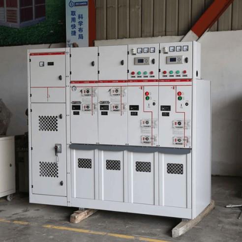
RMU Vehicle: To improve efficiency, technicians designed a dedicated RMU vehicle. The vehicle chassis can be selected as needed, and a single RMU is installed inside the vehicle. The incoming and outgoing ports of this RMU are designed as quick-connect/disconnect types.
2 Steps and Content of the New Bypass Cable Operation
Site Survey: Conduct a pre-operation survey of the work environment to identify and prevent potential hazards.
Bypass Equipment Deployment: Position the bypass RMU vehicle and other bypass operation vehicles. Lay the required bypass cables according to the planned route.
Load Transfer or Power Shutdown Operation: Perform load transfer or a power shutdown (de-energize the supply side power source) for the RMU to be maintained.
Cable Transfer: Disconnect the incoming and outgoing cables from the original RMU and connect them to the cable transfer device. Simultaneously, connect the bypass cables to the transfer device and the RMU vehicle, and verify the phase sequence.
Load Transfer: Energize the supply side power source. Gradually energize the RMU within the RMU vehicle and monitor its operation.
RMU Maintenance or Replacement: Perform maintenance or replacement of the original RMU according to standard procedures.
Second Power Shutdown Operation: De-energize the bypass line power supply. Disconnect the transfer devices. Restore the original RMU cable connections. Conduct necessary tests.
Power Restoration: Restore the original line power supply state.
Characteristics of this operation method:
Small Work Radius: Controlled within 20 meters.
High Operational Efficiency: Small work radius reduces the workload; quick-connect/disconnect couplings significantly improve efficiency.
Reduced Operational Costs: Lower number of equipment sets and personnel required leads to cost reduction.
Short-Duration Outage Operation: Requires two short-duration power outages. Suitable for projects estimated to take over 4 hours if done with a traditional outage; can be scheduled during off-peak electricity hours to maximize advantages.
3 Conclusion
The new bypass cable operation method utilizing the cable transfer approach effectively reduces the work radius, lowers operational costs, and decreases labor intensity during the maintenance or replacement of equipment like RMUs in distribution lines. It is a practical, efficient, and straightforward emergency support technology for distribution networks, worthy of promotion within power distribution systems.
Bypass cable operation is a valuable attempt and a future direction for live-line working technology when facing challenges in cable networks. Although the new method introduced herein has its limitations, it points the way for development. Future research can focus on cable transfer technology and pre-installed bypass connection interfaces on equipment to enable continuous improvement and innovation.