
Brevis Introductio ad Unitates Generales Thermicas
Generatio electricitatis innititur tam renovabilibus quam non-renovabilibus resursis energiae. Unitates generales thermicae repraesentant approprationem traditionalem ad productionem potestatis. In his unitatibus, materiae sicut carbo, energia nuclearis, gas naturalis, biofuel et biogas comburuntur intra caldarium.
Caldarium unitatis generalis est systema extremum complexum. In simplicissima conceptione, id potest visualizari ut camera cuius parietes sunt lineati tubis, per quos aqua perpetuo circulat. Energia thermalis liberata ab combustione materiae intra caldarium transfertur ad hanc aquam. In hoc processu, aqua transformatur in vapor saturatus siccus, characterizatus per altam pressionem (ranging from 150 ksc to 380 ksc, depending on the design) et altam temperaturam (between 530°C and 732°C, subject to design specifications).
Hic vapor saturatus tunc traditur in turbinam, ubi expanditur et eius temperatura cadit. In hoc processu expansionis, vapor transferit suam energiam thermicam ad rotationalem potentiam axis turbine. Fluxus vaporis in turbina regulatur per valvulam regulatoriam, quae regitur a systemate gubernatorio turbine. Itaque, output potentiae activae turbine controllatur a gubernatore. Turbina est copulata cum generatore synchrono.
Generator synchronus convertit potentiam mechanicam turbine in potentiam electricam. Generatores synchro producunt electricitatem ad relativiter bassis voltis, typice in range 11 kV to 26 kV, at nominal frequency. Haec voltage tunc elevatur ad 220 kV/400 kV/765 kV per transformator generativus pro transmissione in rete potestatis. In studiis systematis potestatis, totum hoc systema integratum nominatur unitas generalis.
Control Gubernatoris Turbine (TGC)
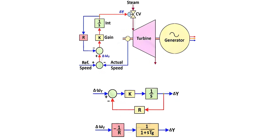
Ut iam dictum, gubernator regulat fluxum potentiae activae in turbina per controllem positionis valvulae regulatoriae. Gubernator hydraulicus potest modelari ut controller integralis qui accipit feedback de actuali velocitate rotatoria turbine. Figura 1 illustrat operationem gubernatoris in modo controlis velocitatis.
Actualis velocitas turbine comparatur contra celeritatem referentiam (corresponding to the nominal grid frequency). Resultans signum erroris velocitatis (∆ωᵣ) tunc traditur ad gubernatorem. Super hoc signum erroris, gubernator adjustat positionem valvulae regulatoriae: si positivum signum erroris detectum est (indicating the actual frequency exceeds the nominal frequency), gubernator paululum claudit valvulam; conversely, it opens the valve when a negative error signal is received.
"R" representat setting droop gubernatoris, typically ranging from 3% to 8%. Mathematica, it is defined as:
R = (per unit change in frequency) / (per unit change in power)
Settings droop sunt critica pro stabili operatione parallela multarum unitatum generalium, quia determinent quomodo onus dividitur intra area controlis. Unitates cum minori valore droop automatica assumunt maiorem partem oneris.
Area Controlis
In systemate potestatis, unitates generales et onera distribuuntur per vastas regiones geographicas. Ad stabilitatem servandam, totum rete dividitur in minores areas controlis (primarie basata geographia). Haec divisio permittit:
Intra area controlis, plures unitates generales et onera coexistunt. Subdividendo systema potestatis in areas controlis servit pluribus obiectivis key:
1. Controlis Frequentiae Oneris
Hoc framework permittit applicationem methodorum controlis oneris-frequentiae ad maintenendum frequentiam retis—conceptum exploratum in maior detail later.
2. Determinatio Interchanges Schedularum
Si generationis areae controlis deficiat respectu demandae oneris, potestas fluit in aream ex vicinis areis controlis via tie lines (et vice versa).
3. Sharing Effectivum Oneris
Demandae oneris variat per diem (e.g., lower at night, peaking in the morning and evening). Areas controlis simplificat processum:
Balance Potestatis
Energia electrica consumitur in real-time (non potest stochari in grande scala). Itaque, balance potestatis est fundamentale requirement:
Power Generated (P₉) = Load Demand (Pd) + Transmission Losses (Pₗ)
Transmission losses typically account for ~2% of generated power and are often neglected when focusing on frequency control. For simplicity, we approximate:
Power Generated (P₉) ≈ Load Demand (Pd)
Variatio Frequentiae
Grid frequency fluctuates due to mismatches between load demand and generation. While minor deviations are stabilized by system inertia, significant gaps (e.g., unit trips, large load changes) can cause frequency to vary by ±5%. Key scenarios include:
In most cases (e.g., unit/line trips, large load connection), demand exceeds generation, causing frequency to drop. Conversely, if a transmission line serving a large load trips, generation may exceed demand, causing frequency to rise. Though the system responds oppositely to these scenarios, understanding frequency dips suffices to grasp both behaviors.
Why Frequency Dips Occur
Two inherent system behaviors drive frequency dips:
1. Load Dampening
Induction motors (e.g., household fans, industrial drives) dominate grid loads. Their power consumption is frequency - dependent: a 1% frequency reduction typically reduces active power consumption by ~2% in large systems. When new loads connect, frequency drops, and existing induction loads automatically consume less power—partially mitigating the demand - generation gap.
2. Kinetic Energy Release from Turbine - Generator (TG) Sets
Conventional TG sets have massive rotors (often >25 tonnes) spinning at 3000 RPM (for 50Hz grids). When demand exceeds generation, these rotors temporarily supply stored kinetic energy (for 3–5 seconds, depending on inertia). As rotors slow down, grid frequency drops.
Frequency Control
Load - frequency control (LFC) restores grid frequency to its nominal value after demand - generation mismatches. Two tiers of control exist:
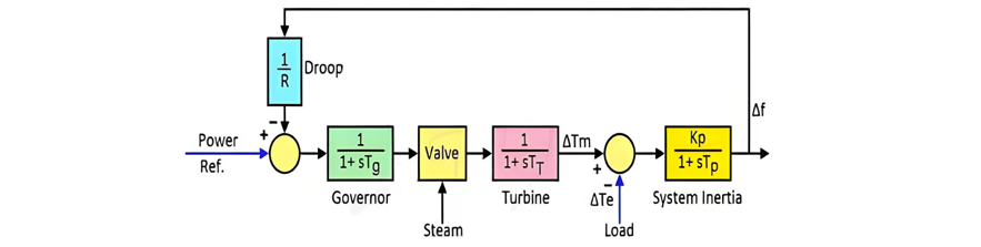
1. Primary Frequency Control
At the unit level, the turbine's governing system adjusts speed (and thus frequency). As shown earlier, each unit modulates steam input based on frequency deviations. The full primary control loop for a generating station is depicted in the figure below.
2. Secondary Frequency Control
This involves coordinated control across multiple units in different control areas, ensuring long - term frequency stability and optimal load sharing.
Primary Frequency Control Limitations
Primary frequency control alone results in a steady - state frequency deviation, influenced by the governor droop characteristic and load frequency sensitivity. This occurs because individual units adjust speed without considering where new loads are connected or how much load is added. Without such contextual assessment, power balance cannot be fully restored, and frequency deviation persists. Following primary control actions, the steady - state frequency error may be either positive or negative.
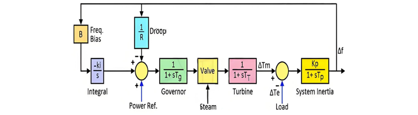
Secondary Frequency Control
Restoring system frequency to its nominal value requires secondary control, which accounts for new load locations and adjusts reference setpoints for selected units. When load increases in a control area, generation within that area must rise to:
To achieve this:
Once revised load setpoints are issued, units begin adjusting generation. Due to the mechanical nature of power production, it takes 25–30 minutes for units to reach their scheduled outputs. When all generating stations achieve target generation, power balance is reinstated, and frequency returns to nominal.
The overall response of the system with the primary and secondary frequency control can be understood by the graph below.
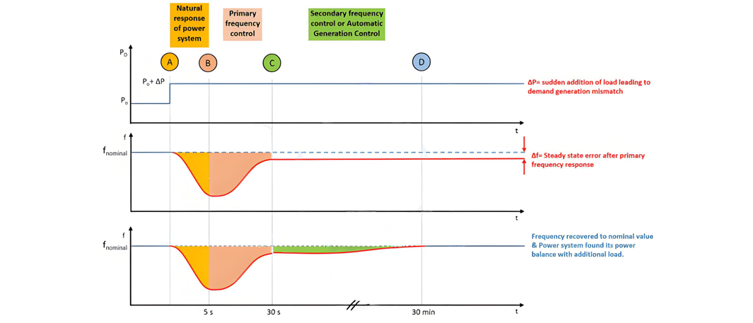
System Response to Load Increase (A-B-C-D)
A-B: Transient Kinetic Energy Release
Before point A, the system operates in power balance. At point A, load suddenly increases from P₀ to P₀ + ∆P. A 3–5 second delay occurs before the governor responds. During this interval, the rotor's stored kinetic energy supplies the excess load, causing rotor speed to drop and frequency to dip to a minimum value f₁.
B-C: Primary Frequency Control Action
At ~5 seconds, the governor initiates speed control, increasing steam input to restore rotor speed. This phase lasts 20–25 seconds (dependent on the frequency dip magnitude). As discussed, primary control alone leaves a steady - state frequency error ∆f due to governor droop.
C-D: Secondary Frequency Control (AGC Activation)
Once frequency stabilizes, secondary control (via AGC) adjusts generation for selected units in each control area. This process considers:
Generation adjustments are limited by the units' design ramp rates, taking several minutes to complete. Upon finishing, scheduled interchanges return to pre - calculated values, and the system achieves a new power balance with nominal frequency.


